Mixed grading ultra-low emission combustor

A burner, ultra-low technology, applied in the direction of combustion chamber, combustion method, combustion equipment, etc., can solve the problems of poor combustion stability, high thermal NOx emissions, etc., to improve flame stability, reduce NOx generation, reduce combustion oscillation risk effect

Active Publication Date: 2019-12-20
中国船舶重工集团公司第七0三研究所
View PDF8 Cites 3 Cited by
  • Summary
  • Abstract
  • Description
  • Claims
  • Application Information

AI Technical Summary

Problems solved by technology

[0003] In order to solve the problems of poor combustion stability under low working conditions of gas turbines and high therma

Method used


Image

  • Mixed grading ultra-low emission combustor
  • Mixed grading ultra-low emission combustor
  • Mixed grading ultra-low emission combustor

Examples


specific Embodiment approach 1

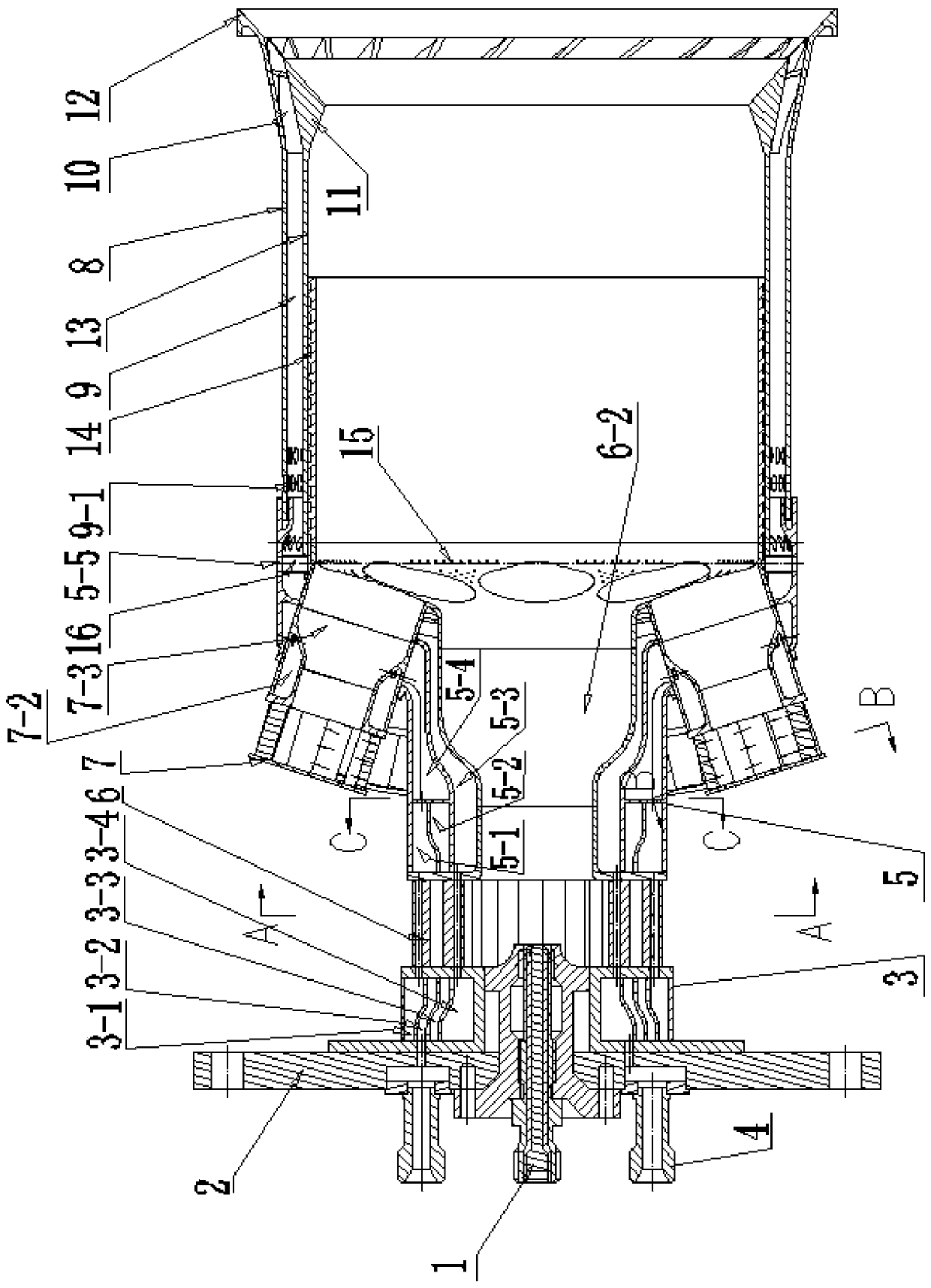
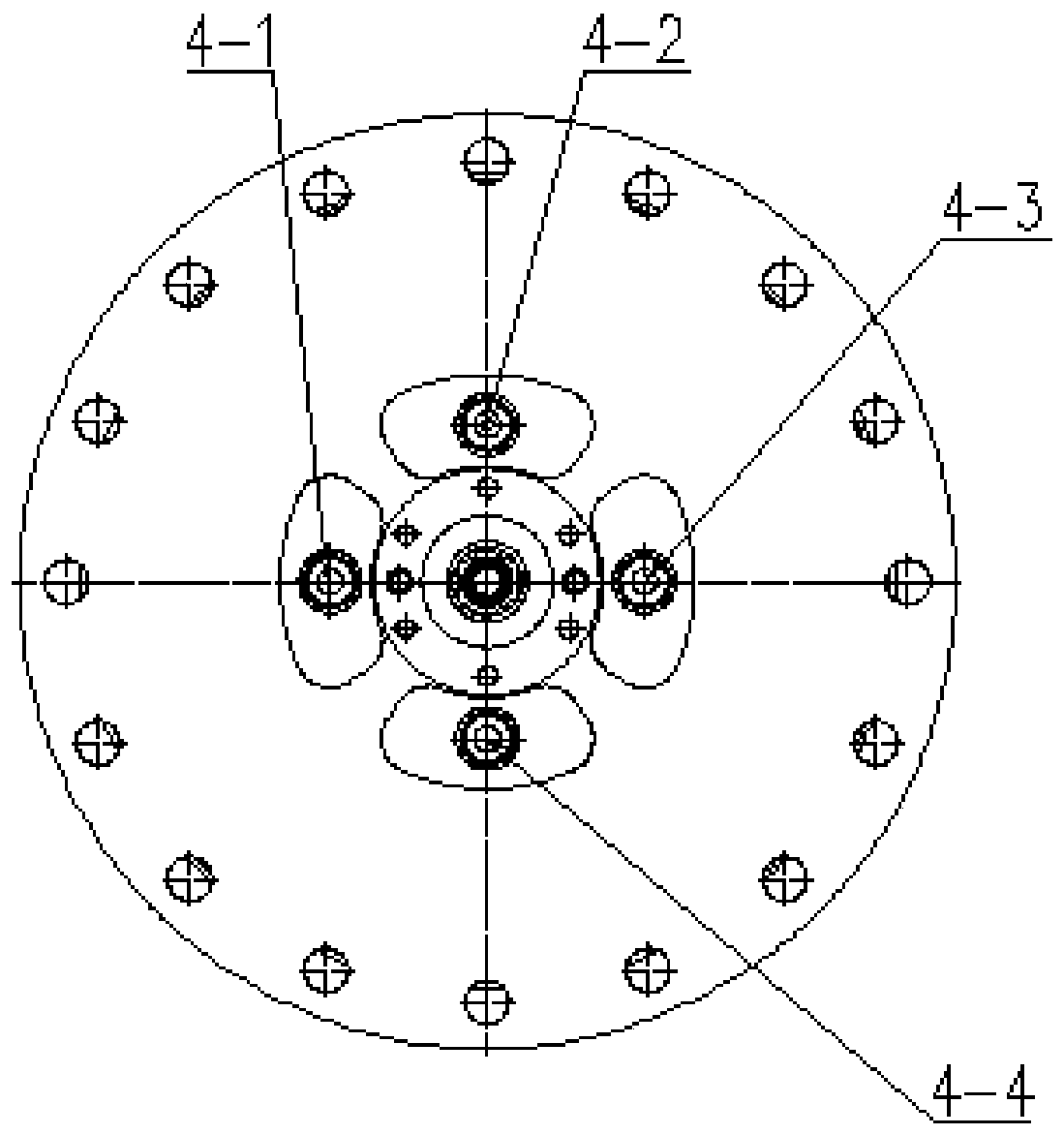
[0018] Specific implementation mode one: combine Figure 1 to Figure 5 Describe this embodiment. This embodiment includes an igniter 1, a casing front flange 2, a first fuel chamber casing 3, four fuel gas joints 4 and a second fuel chamber casing 5. The igniter 1 is installed in the casing In the middle of the left side of the front flange 2, four fuel gas joints 4 are evenly distributed in the circumferential direction on the front flange 2 of the casing, and the four fuel gas joints 4 are located on the outside of the igniter 1. The first fuel chamber housing 3 and The casing front flange 2 is connected, and the mixed staged ultra-low emission burner also includes a first-stage sub-burner, a second-stage sub-burner and a third-stage sub-burner, and the first-stage sub-burner , the second fuel chamber casing 5 , the second-stage sub-burner and the third-stage sub-burner are connected sequentially from left to right, and the first-stage sub-burner is connected with the first ...

specific Embodiment approach 2

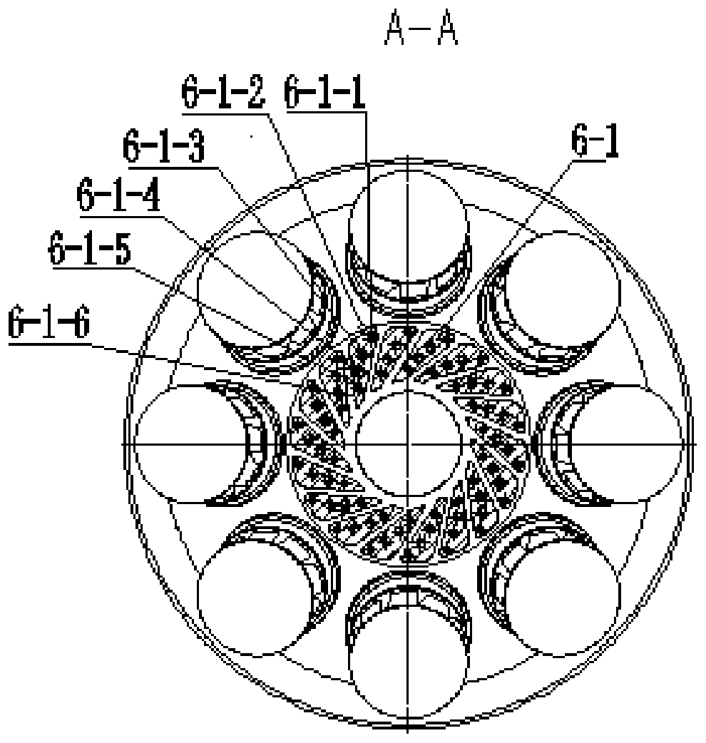
[0021] Specific implementation mode two: combination figure 1 and image 3 To illustrate this embodiment, the first-stage sub-combustor in this embodiment is composed of a first radial swirler 6, and a plurality of first-stage swirler blades 6- 1. A plurality of first-stage swirler blades 6 - 1 are evenly distributed along the circumferential direction of the first radial swirler 6 .

[0022] Other components and connections are the same as those in the first embodiment.

specific Embodiment approach 3

[0023] Specific implementation mode three: combination image 3 Describe this embodiment, the first swirler blade 6-1 of this embodiment adopts cavity design, the first fuel injection hole 6-1-1 is opened at the front edge of the first swirler blade 6-1, each swirler The first fuel blade hole 6-1-2, the second fuel blade hole 6-1-3, the third fuel blade hole 6-1-4 and the fourth fuel blade hole 6-1- 5. A first flow passage 6-1-6 is provided between every two adjacent first-stage swirler blades 6-1.

[0024] The other components are the same as those in Embodiment 1 or 2 in terms of connections.


PUM


Abstract

The invention relates to a combustor, in particular to a mixed grading ultra-low emission combustor, and aims to solve the problems of poor combustion stability of a gas turbine under a low working condition and high thermal NOx emission under a high working condition. The mixed grading ultra-low emission combustor comprises an igniter, a casing front flange, a first fuel cavity shell, four fuel gas connectors and a second fuel cavity shell, wherein the igniter is arranged in the middle of the left side of the casing front flange; the four fuel gas connectors are uniformly arranged on the casing front flange in the circumferential direction, and the four fuel gas connectors are arranged on the outer side of the igniter; the first fuel cavity shell is connected with the casing front flange;the mixed grading ultra-low emission combustor also comprises a first-stage sub-combustor, a second-stage sub-combustor and a third-stage sub-combustor; the first-stage sub-combustor, the second fuelcavity shell, the second-stage sub-combustor and the third-stage sub-combustor are sequentially connected from left to right; and the first-stage sub-combustor is connected with the first fuel cavityshell. The mixed grading ultra-low emission combustor is good in combustion stability under the low working condition, can realize ultra-low emission under the high working condition, and has large-scale application and popularization values.

Description

technical field [0001] The invention relates to a burner, in particular to a mixed staged ultra-low emission burner, and belongs to the technical field of gas turbines. Background technique [0002] As an advanced power device with small size, high power and fast start-up speed, gas turbine is widely used in electric power, petrochemical, metallurgy, aerospace, shipbuilding and other fields. Since the gas turbine technology was first proposed in the 1930s, it has experienced more than 80 years of development, and has significantly improved in terms of power, efficiency, and reliability. In recent years, with the intensification of environmental pollution, governments of various countries have begun to formulate increasingly stringent pollutant emission standards, which pose new challenges to gas turbine technology. The main pollutants of industrial gas turbines include nitrogen oxides and carbon monoxide. In order to reduce the formation of thermal NOx, lean premixed combu...

Claims


Application Information

Patent Timeline
IPC IPC(8): F23R3/34F23R3/58
CPCF23R3/346F23R3/58
Inventor 程旭李东明潘宏伟林枫李雅军李名家梁晨
Owner 中国船舶重工集团公司第七0三研究所
Why Eureka
Try Eureka