PU tube detection device used for high-end equipment manufacturing
A tube detection and measurement device technology, which is applied in the field of high-end equipment manufacturing PU tube detection devices, to achieve the effects of improved efficiency, high precision, and simple operation
- Summary
- Abstract
- Description
- Claims
- Application Information
AI Technical Summary
Problems solved by technology
Method used
Image
Examples
Embodiment 1
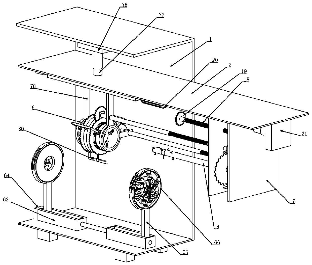
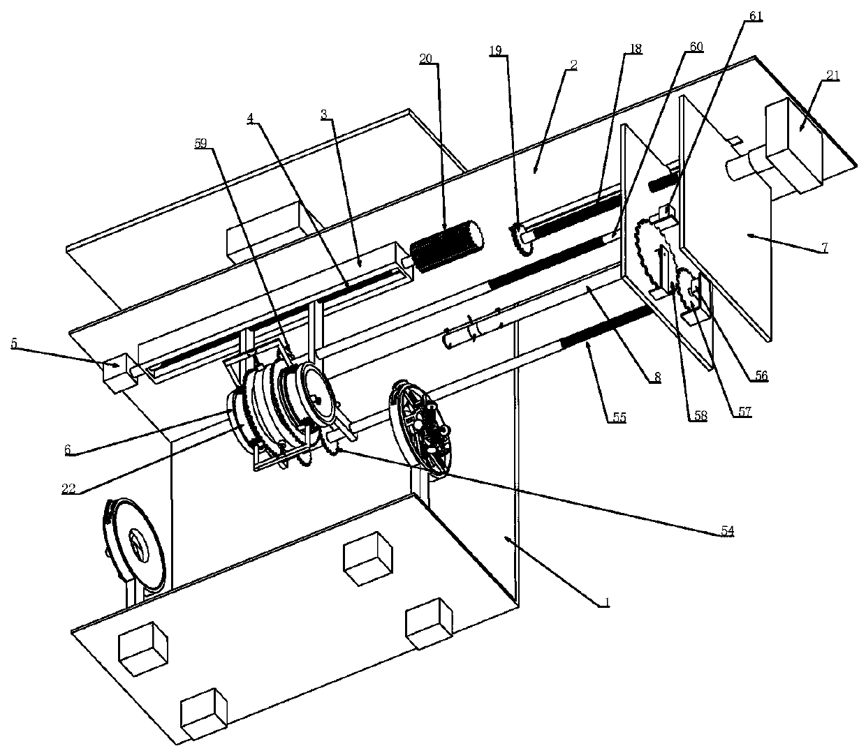
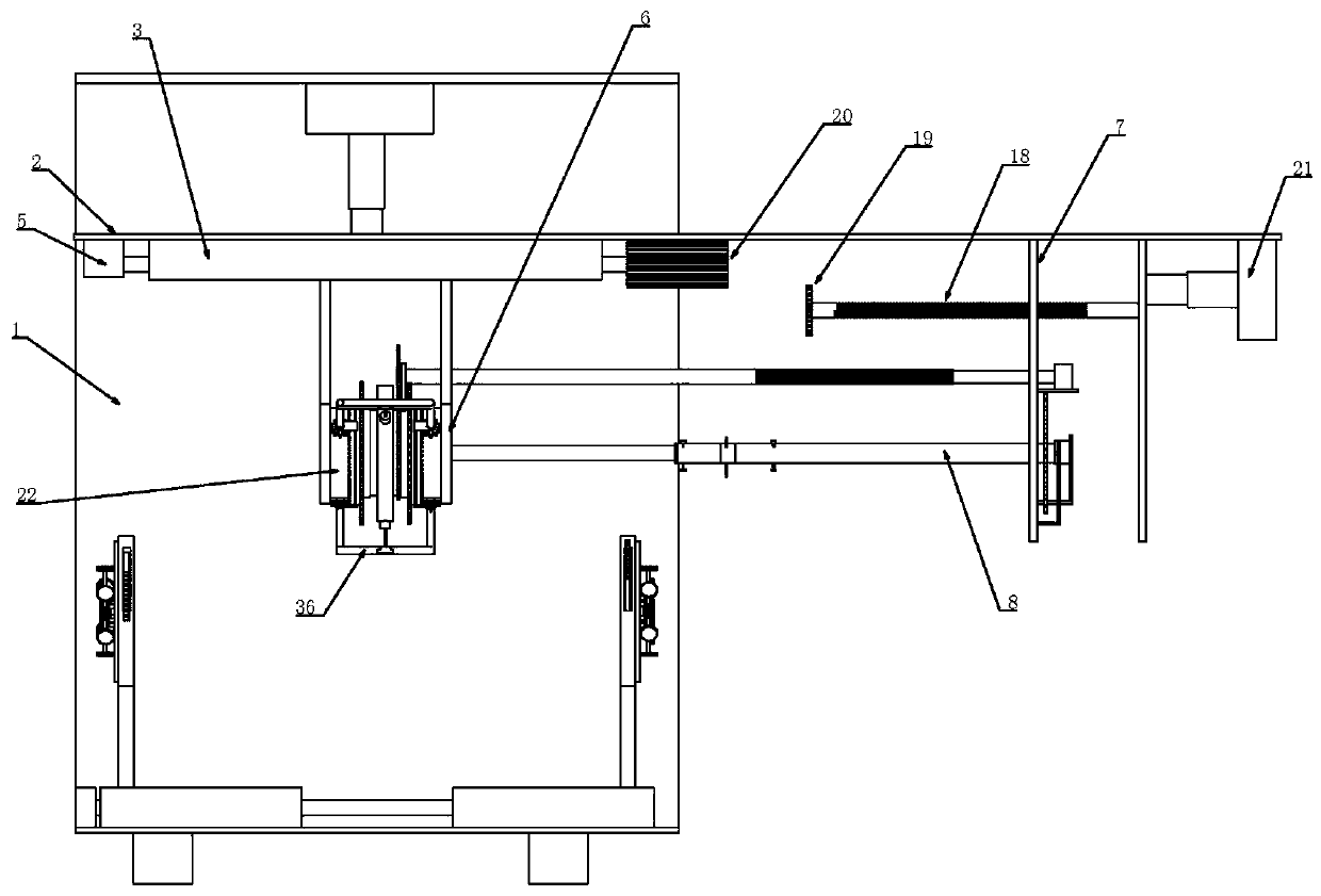
[0039] Embodiment one, combined with the attached Figure 1-18 , used for high-end equipment manufacturing PU tube detection device, including a bracket 1, characterized in that a set of clamping devices are installed on the bottom of the bracket 1, for clamping and fixing the PU tube sample to be tested, because the PU tube belongs to soft It is a high-quality tubular material, so it is necessary to clamp and fix the two ends of the PU tube when testing the airtightness and the thickness of the tube wall. Therefore, adding a clamping device is equivalent to erecting the two ends of the PU tube. The bracket 1 The upper vertical sliding fits a moving plate 2, and the moving plate 2 relies on a T-shaped slider for vertical sliding fit, so that the moving plate 2 can only move in the vertical direction. direction displacement, a lifting device for driving the moving board 2 is connected between the moving board 2 and the top of the support 1, and the lifting device drives the mov...
Embodiment 2
[0043] Embodiment two, on the basis of embodiment one, in conjunction with the attached Figure 1-18 , the outer diameter pinch measuring device includes a fixed cylinder 22 installed in the fixed ring 6, the fixed cylinder 22 is fixedly installed in the fixed ring 6, the external rotation of the fixed cylinder 22 is connected to a rotating ring 23, the fixed cylinder 22 There is an annular chute with a T-shaped cross-section on the outer wall, and the chute is slidably matched with a slider with a T-shaped cross-section connected in the rotating ring 23, so that the rotating ring 23 can only move along the circumference of the fixed cylinder 22. direction, the rotating ring 23 is externally connected with multiple sets of sleeves 24 that rotate radially through the fixed cylinder 22, and the sleeve 24 is externally fixed with a second gear 25, and multiple sets of second gears 25 meshes with the first ring gear 26 coaxially installed on the rotating ring 23, and the inner thr...
Embodiment 3
[0046] Embodiment three, on the basis of embodiment one, in conjunction with the attached Figure 1-18 , the inner diameter pinch measuring device includes a quill 8 fixedly installed on the left vertical plate 7, a rotary cylinder 41 is rotatably connected inside the quill 8, and a rotary cylinder 41 is rotatably connected with a Swivel 42, said swivel 42 is externally rotated and sleeved with a circular ring 43, an annular groove structure is formed on the rotating cylinder 41 in the axial direction, and the rotation of the swivel 42 is set in this groove structure, and the swivel 42 The outer ring 43 is flush with the outer diameter of the sleeve shaft 8, and both sides of the ring 43 are intermittently matched with the sleeve shaft 8. The coaxial rotation of the rotating drum 41 is sleeved with a ring fixedly installed on the vertical plate 7. Connecting rod 44, the connecting rod 44 is rotatably set in the drum 41, it is fixedly installed on the vertical plate 7 at the en...
PUM
 Abstract
Description
Claims
Application Information
 - R&D
- Intellectual Property
- Life Sciences
- Materials
- Tech Scout
- Unparalleled Data Quality
- Higher Quality Content
- 60% Fewer Hallucinations
Browse by: Latest US Patents, China's latest patents, Technical Efficacy Thesaurus, Application Domain, Technology Topic, Popular Technical Reports.
© 2025 PatSnap. All rights reserved.Legal|Privacy policy|Modern Slavery Act Transparency Statement|Sitemap|About US| Contact US: help@patsnap.com


