Waste heat boiler vibration control system and method

A waste heat boiler and control system technology, applied in general control system, control/regulation system, program control, etc., can solve problems such as unsatisfactory rapping effect, adjustment of rapping grouping or sequence, etc.

Pending Publication Date: 2019-12-20
紫金铜业有限公司
View PDF8 Cites 0 Cited by
  • Summary
  • Abstract
  • Description
  • Claims
  • Application Information

AI Technical Summary

Problems solved by technology

Due to the original scheme of fixed grouping and sequential rapping, technicians cannot adjust the rapping group or sequence according to the production process conditions and the distribution of boiler ash, and the rapping effect is not ideal

Method used


Image

  • Waste heat boiler vibration control system and method
  • Waste heat boiler vibration control system and method

Examples


Embodiment 1

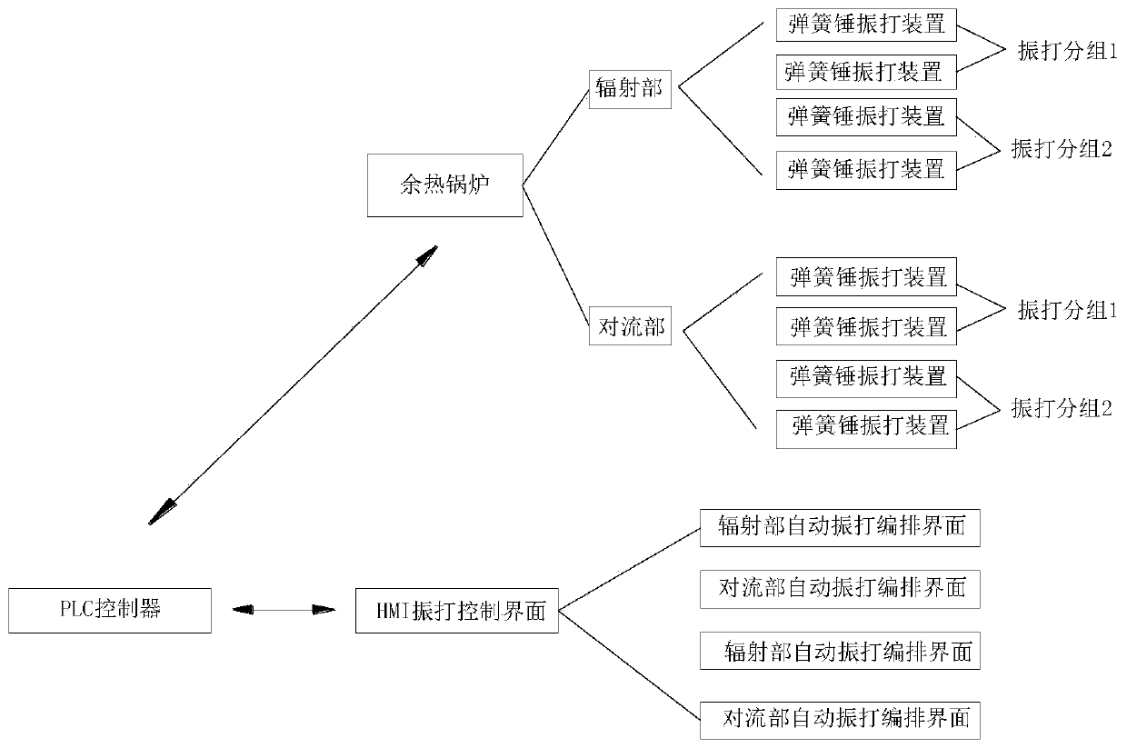
[0028] This embodiment provides a waste heat boiler rapping control system, such as figure 1 shown, including:

[0029] Waste heat boiler: equipped with several spring hammer rapping devices, all spring hammer rapping devices are divided into several rapping groups, and the rapping time and interval time of each group of rapping groups can be adjusted independently;

[0030] Further, in this embodiment, the waste heat boiler includes a radiation part and a convection part, and the radiation part and the convection part are respectively provided with several spring hammer rapping devices, and the rapping groups in the radiation part and the convection part The rapping groups of each form an independent rapping cycle.

[0031] Taking the medium-sized flash furnace waste heat boiler as an example, five rapping groups are set in the radiation part, and three rapping groups are set in the convection part. In the radiation part, the vibration is cyclically rapped in the order of 1...

Embodiment 2

[0045] This embodiment provides a method for utilizing the waste heat boiler rapping control system as described in Embodiment 1, including the following steps:

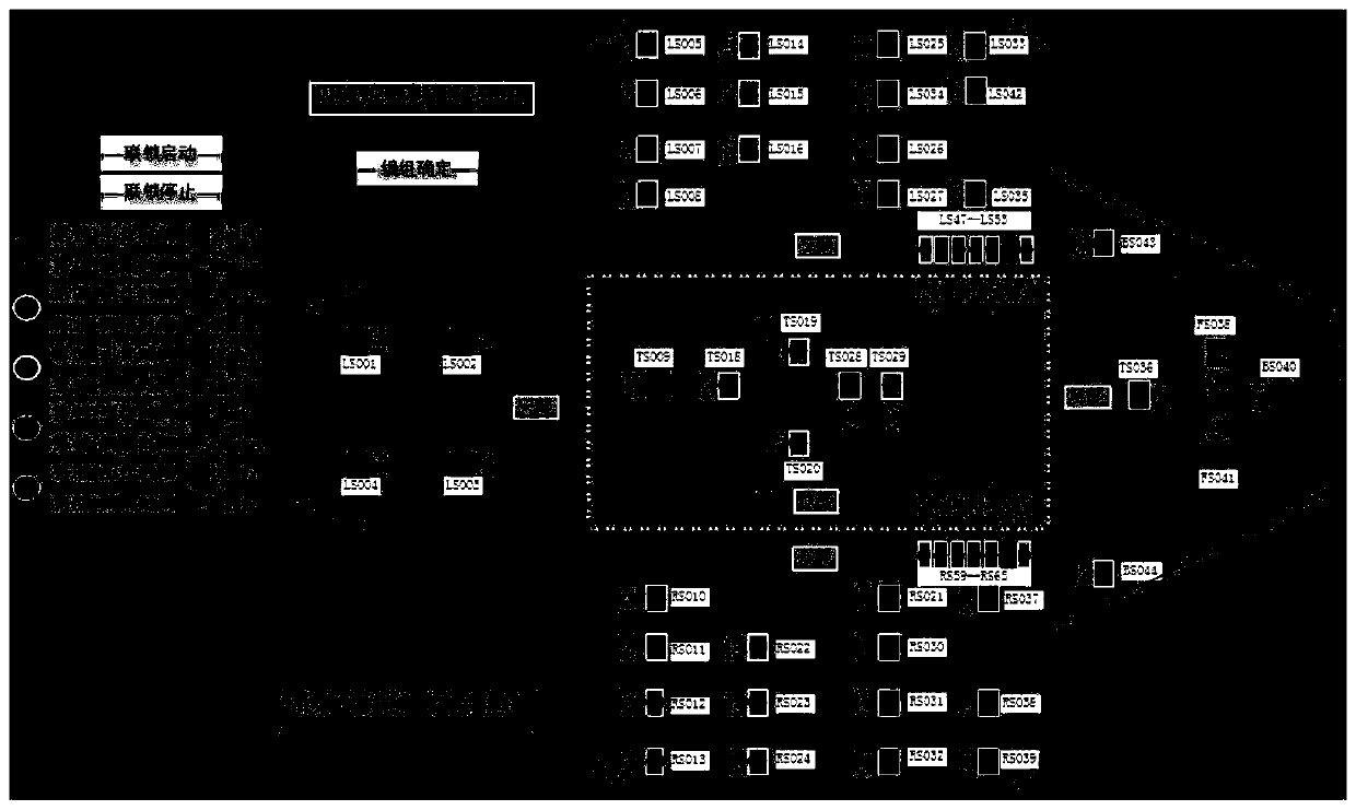
[0046] S1. When the automatic rapping mode is required, the craftsmen set the rapping points of each spring hammer rapping device on the automatic rapping arrangement interface through the group input module according to the production process conditions and the distribution of boiler ash group, and set the rapping time and interval time of each rapping group by setting the input module;

[0047] S2. The HMI rapping control device sends the rapping group to which each spring hammer rapping device belongs, the rapping time and interval time of each group of rapping groups set on the automatic rapping arrangement interface by the technician to the PLC controller;

[0048] S3. The PLC controller controls each rapping group to start rapping in order according to the rapping group to which each spring hammer rapping devic...


PUM


Abstract

The invention discloses a waste heat boiler vibration control system and method. The waste heat boiler vibration control system includes a waste heat boiler which is provided with a plurality of spring hammer vibration devices, an HMI (Human Machine Interface) vibration control device configured to display an HMI vibration control interface which comprises an automatic vibration arrangement interface, and a PLC (Programmable Logic Controller) communicably connected to the HMI vibration control device; wherein the spring hammer vibration devices are divided into a plurality of vibration groups,and vibration time and interval time of the vibration groups are independent and adjustable; and the PLC is configured to store serial number of each spring hammer vibration device, receive control instructions, grouping instructions for the vibration groups and setting instructions for the vibration time and interval time of each vibration group transmitted by the HMI vibration control device, and control each vibration group to perform vibration in sequence according to the instructions. According to the waste heat boiler vibration control system and method, technologists can perform real-time grouping and adjustment for a boiler vibration device based on different production periods and conditions and ash deposition condition of the boiler, thus the effects of enhancing vibration effect, clearing ash deposition of the boiler and ensuring smooth operation of copper pyrometallurgical smelting production are achieved.

Description

technical field [0001] The invention relates to the field of electrical automatic control, in particular to a waste heat boiler rapping control system and method. Background technique [0002] The waste heat boiler is an important equipment in the copper fire smelting process. The high-temperature flue gas of about 1200 °C generated during the smelting process needs to be cooled and dusted by the waste heat boiler, and then enters the electrostatic precipitator for dust removal, and then is sent to the sulfuric acid process by the induced draft fan for flue gas production. acid; the metal dust in the flue gas is settled and collected by the waste heat boiler and finally returned to the smelting furnace for recycling; the heat energy in the flue gas is converted into high-pressure steam in the waste heat boiler and sent to the turbine generator for power generation through the pipe network. In order to collect the dust in the flue gas, a large number (about 100 sets of medium...

Claims


Application Information

Patent Timeline
Patent Type & Authority Applications(China)
IPC IPC(8): G05B19/05
CPCG05B19/058G05B2219/163
Inventor 林仁华黄宜标李涛林福坤曾令通邱勤生
Owner 紫金铜业有限公司
Why Eureka
Try Eureka