Capacitor vapor deposition negative pressure gold-plating device and gold-plating method thereof

A vapor deposition and capacitor technology, applied in the direction of capacitors, capacitor manufacturing, laminated capacitors, etc., can solve the problems of long travel of conductive materials, limited spray gun coverage, and changes, so as to improve conductivity, better forming effect, and forming The effect of uniform thickness

Active Publication Date: 2019-12-20
HUANGSHAN SHENGE ELECTRONICS TECH
View PDF15 Cites 2 Cited by
  • Summary
  • Abstract
  • Description
  • Claims
  • Application Information

AI Technical Summary

Problems solved by technology

[0004] There are defects in the traditional gold spraying operation: 1. Since the gold spraying process is point-to-face processing, the coverage of the spray gun is limited, and the conductive material sprayed from the spray gun spreads around. The central area has higher strength and a shorter stroke, which is easy to stick It fits on the cell gap to form a qualified coating, but the conductive material at the edge has a long stroke, resulting in insufficient final potential energy, and the thickness and strength of the coating will be affected, which will eventually lead to insufficient uniformity of the processed metal conductive layer of the cell and poor conductivity. Performance decline; 2. Due to the weak bonding ability between the initially sprayed conductive material and the surface of the battery cell, one-time gold spraying process is used. Once the initial conductive layer is not well formed, subsequent gold spray coatings will follow. Changes , poor reliability

Method used


Image

  • Capacitor vapor deposition negative pressure gold-plating device and gold-plating method thereof
  • Capacitor vapor deposition negative pressure gold-plating device and gold-plating method thereof
  • Capacitor vapor deposition negative pressure gold-plating device and gold-plating method thereof

Examples


Embodiment Construction

[0041] In order to make the object, technical solution and advantages of the present invention more clear, the present invention will be further described in detail below in conjunction with the examples. It should be understood that the specific embodiments described here are only used to explain the present invention, not to limit the present invention.

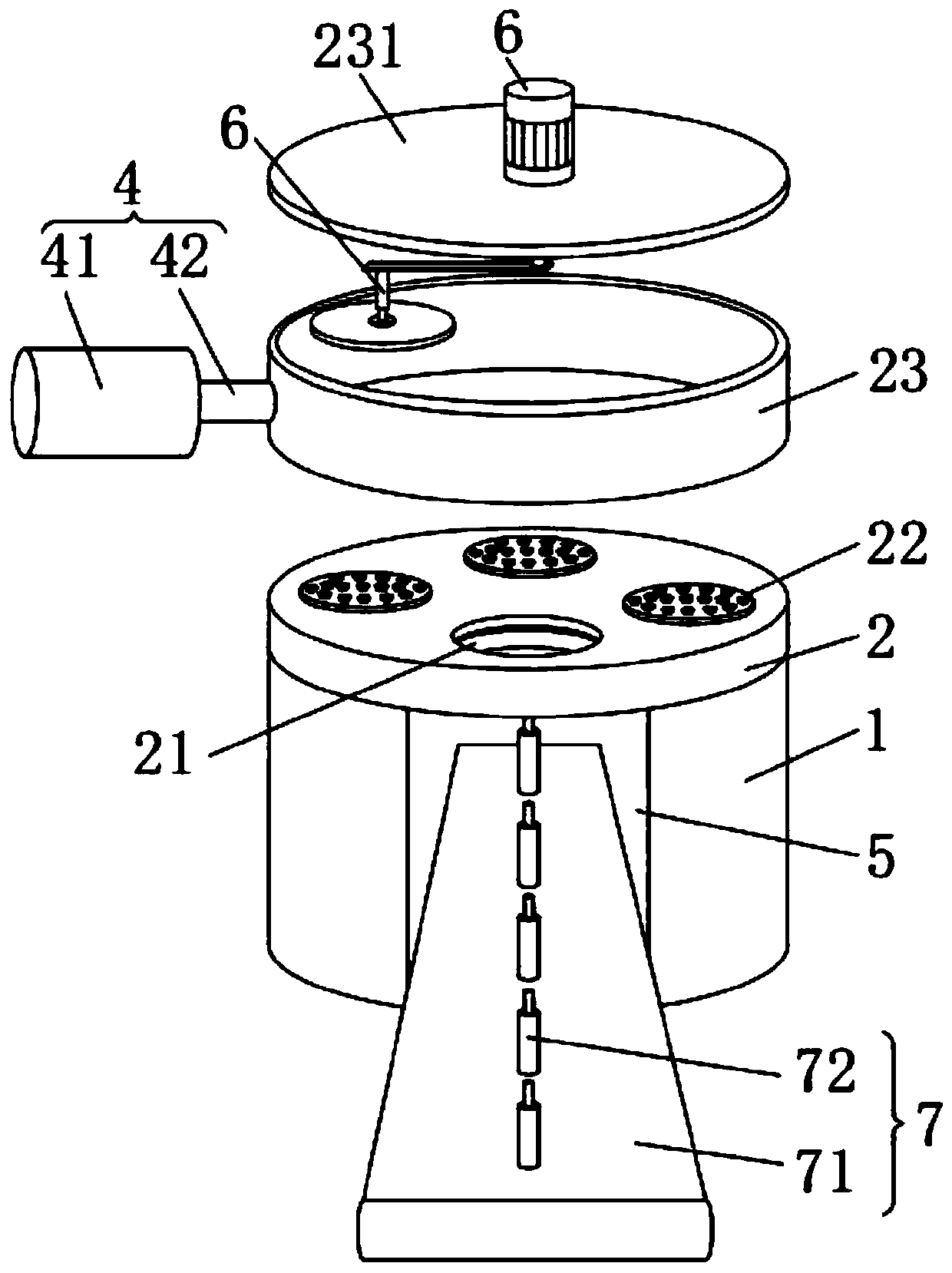
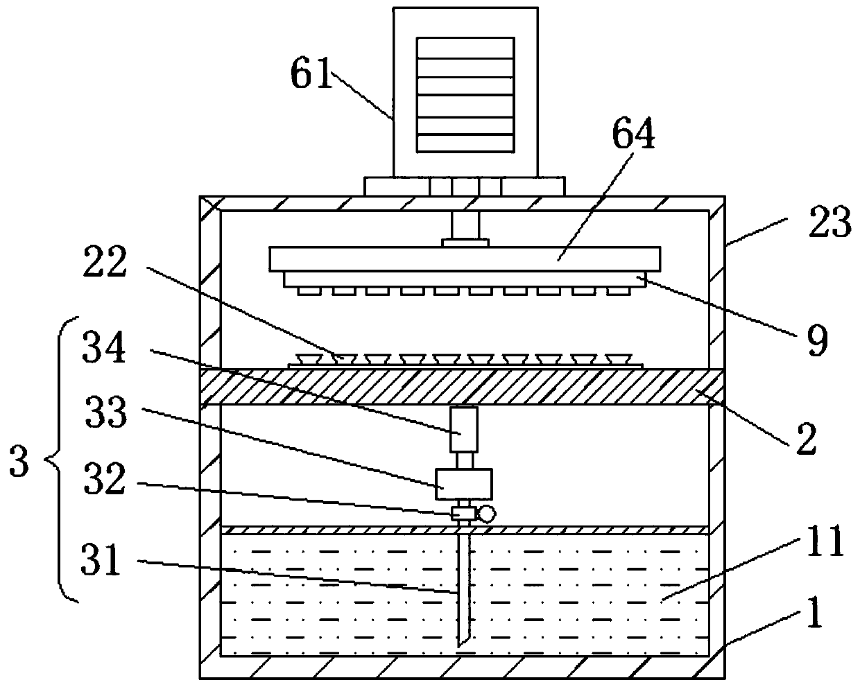
[0042]The capacitor vapor deposition negative pressure gold plating device includes a tank body 1; the inner bottom of the tank body 1 is provided with a molten material storage chamber 11 with a sealed structure; the top of the tank body 1 is provided with a circular hollow structure operating seat 2, The surface of the operating seat 2 is provided with a sealing cover 23; the outside of the sealing cover 23 is connected to a vacuum mechanism 4; the sealing cover 23 is a processing area for depositing gold plating, and the vacuum mechanism 4 is used to pump the inside of the sealing cover 23 to a vacuum state;

[0043] The...


PUM


Abstract

The invention discloses a capacitor vapor deposition negative pressure gold-plating device and a gold-plating method thereof. The gold-plating device comprises multiple exhaust disks and feeding and blanking ports in annular arrangement distribution; the bottom of each exhaust disk is communicated with a gold-plating mechanism; the bottom end of each gold-plating mechanism communicates with a molten material storage chamber, and an outlet end of the gold-plating mechanism is arranged in a seal cover; the gold-plating mechanism is used for pumping quantitative molten material and heating the molten material as the gaseous material to eject; a station conversion mechanism is arranged in the seal cover, a bottom surface of the station conversion mechanism is magnetically adsorbed and connected with an irony mold plate, multiple core main bodies are embedded into the bottom surface of the mold plate; and the station conversion mechanism is used for driving the mold plate to circularly andorderly covert between multiple groups of exhaust disks and feeding and blanking ports. The vapor deposition processing can be performed on the cell end surface, so that the molding thickness of an electrode surface is more uniform and free from missing, and the conductive performance of a conductive plane is improved.

Description

technical field [0001] The invention belongs to the technical field of processing metallized film capacitors, in particular to a capacitor vapor deposition negative pressure gold plating device and a gold plating method thereof. Background technique [0002] Gold spraying refers to the use of heat sources such as electric arc or flame to melt all kinds of solder materials to be sprayed and atomize them under the action of high-pressure air; the crushed metal particles are sprayed at high speed on the capacitor core assembly surface with high sensitivity to heat energy In the film gap, the end face of the core group forms an equipotential metal electrode surface from the inner winding layer to the outer winding layer, providing a bridging platform for electrode extraction; [0003] The traditional gold spraying method is to insert multiple batteries into the surface of the template by the worker, and then install the template at the loading and unloading station in the gold s...

Claims


Application Information

Patent Timeline
IPC IPC(8): H01G13/00H01G4/252H01G4/33C23C4/08C23C4/123
CPCC23C4/08C23C4/123H01G4/252H01G4/33H01G13/006
Inventor 张宏远
Owner HUANGSHAN SHENGE ELECTRONICS TECH
Why Eureka
Try Eureka