A Parallel Coupled Slow Wave Circuit Return Wave Tube

A slow-wave circuit and return-wave tube technology, which is applied in the field of return-wave tubes, can solve the problems of inability to solve current efficiency, poor tube flow, difficulty in focusing, etc., so as to increase the available current, improve the interaction efficiency, and improve the output. The effect of power and efficiency

Active Publication Date: 2020-10-16
UNIV OF ELECTRONICS SCI & TECH OF CHINA
View PDF3 Cites 0 Cited by
  • Summary
  • Abstract
  • Description
  • Claims
  • Application Information

AI Technical Summary

Problems solved by technology

[0005] Microstructure processing methods include various mechanical processing methods, UV-LIGA and DRIE, etc., but these processing methods cannot solve the problem of current efficiency
The increase in current density is achieved by improving the performance of various beamforming systems. Although it increases the total current that the return wave tube can utilize, this increase is limited and makes beamforming difficult. Circulation deterioration
Although various improved high-frequency structures have been proposed, improving various slow-wave circuits can only partially improve the performance of the return wave tube, and cannot greatly improve the output power and efficiency of the return wave tube.
These existing research and technical means can only improve or alleviate the difficulties caused by the size co-existence effect to a certain extent.

Method used


Image

  • A Parallel Coupled Slow Wave Circuit Return Wave Tube
  • A Parallel Coupled Slow Wave Circuit Return Wave Tube
  • A Parallel Coupled Slow Wave Circuit Return Wave Tube

Examples


Embodiment Construction

[0036] Specific embodiments of the present invention will be described below in conjunction with the accompanying drawings, so that those skilled in the art can better understand the present invention. It should be noted that in the following description, when detailed descriptions of known functions and designs may dilute the main content of the present invention, these descriptions will be omitted here.

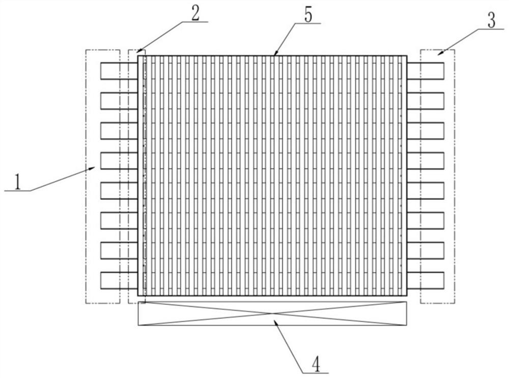
[0037] figure 1 It is a structural schematic diagram of a specific embodiment of the return wave tube of the parallel coupling slow wave circuit of the present invention.

[0038] In this example, if figure 1 As shown, the return wave tube of the parallel coupling slow wave circuit of the present invention includes: a multi-electron beam electron gun 1, a reflection output port, that is, a return wave tube output port 2, a collector 3, a focusing system 4, a plurality of slow wave structures and a plurality of coupling structures A parallel coupled slow wave circuit 5 is ...


PUM


Abstract

The invention discloses a return wave tube of a parallel coupling slow wave circuit, which adopts a multi-electron beam electron gun and a plurality of slow wave structures, and superimposes the return waves of each slow wave structure obtained, and at the same time, in two adjacent slow wave A coupling structure is placed between the structures, the coupling structure is a metal barrier, and there are openings in the space between the square ring gates in the coupling structure, so that multiple slow-wave structures are combined to form a parallel coupled slow-wave circuit. The coupling structure of the parallel slow-wave circuit makes the high-frequency field and the space charge field between the slow-wave structures effectively coupled, thereby achieving the purpose of locking the phase of the high-frequency field between the slow-wave structures and improving the interaction efficiency, so that the output power is greater than The simple addition of the power of each slow wave structure greatly improves the output power and efficiency.

Description

technical field [0001] The invention belongs to the technical field of vacuum electronic devices, and more specifically relates to a return wave tube. The high frequency slow wave structure of the return wave tube is a parallel coupled slow wave circuit. Background technique [0002] As a classic microwave source device, the return wave tube is a high-power, high-efficiency radiation source. In addition, the return wave tube also has the characteristics of good monochromatic characteristics, signal stability, frequency tuning characteristics and compact structural appearance. Several THz can be achieved. At present, in the 1THz frequency band, the return wave tube can only generate power output in the order of milliwatts, which cannot meet the needs of communication, biology and other applications. [0003] When the back wave tube develops towards the high-frequency band, the main reason for the reduction of its power level is the size co-existence effect of the vacuum mic...

Claims


Application Information

Patent Timeline
Patent Type & Authority Patents(China)
IPC IPC(8): H01J25/34
CPCH01J25/34
Inventor 赵越殷海荣程均徐进岳玲娜赵国庆王文祥魏彦玉
Owner UNIV OF ELECTRONICS SCI & TECH OF CHINA
Why Eureka
Try Eureka