Ultra-wideband double-ridge horn antenna for 1-40GHz frequency band

A ridge horn and ultra-wideband technology, which is applied in the field of ultra-wideband double-ridge horn antennas, can solve the problems of poor matching performance in the low frequency band, main lobe splitting gain, and drop, and achieve the effect of improving matching performance and widening bandwidth

Inactive Publication Date: 2019-12-20
HARBIN INST OF TECH
View PDF7 Cites 10 Cited by
  • Summary
  • Abstract
  • Description
  • Claims
  • Application Information

AI Technical Summary

Problems solved by technology

[0005] The present invention aims to solve the problems of poor matching performance in the low-frequency band, splitting of the main lobe of the pattern in the high-frequency band and decrease in gain of the existing double-ridge horn antenna, and further provides an ultra-wideband double-ridge horn antenna for the 1-40GHz frequency band

Method used


Image

  • Ultra-wideband double-ridge horn antenna for 1-40GHz frequency band
  • Ultra-wideband double-ridge horn antenna for 1-40GHz frequency band
  • Ultra-wideband double-ridge horn antenna for 1-40GHz frequency band

Examples


specific Embodiment approach 1

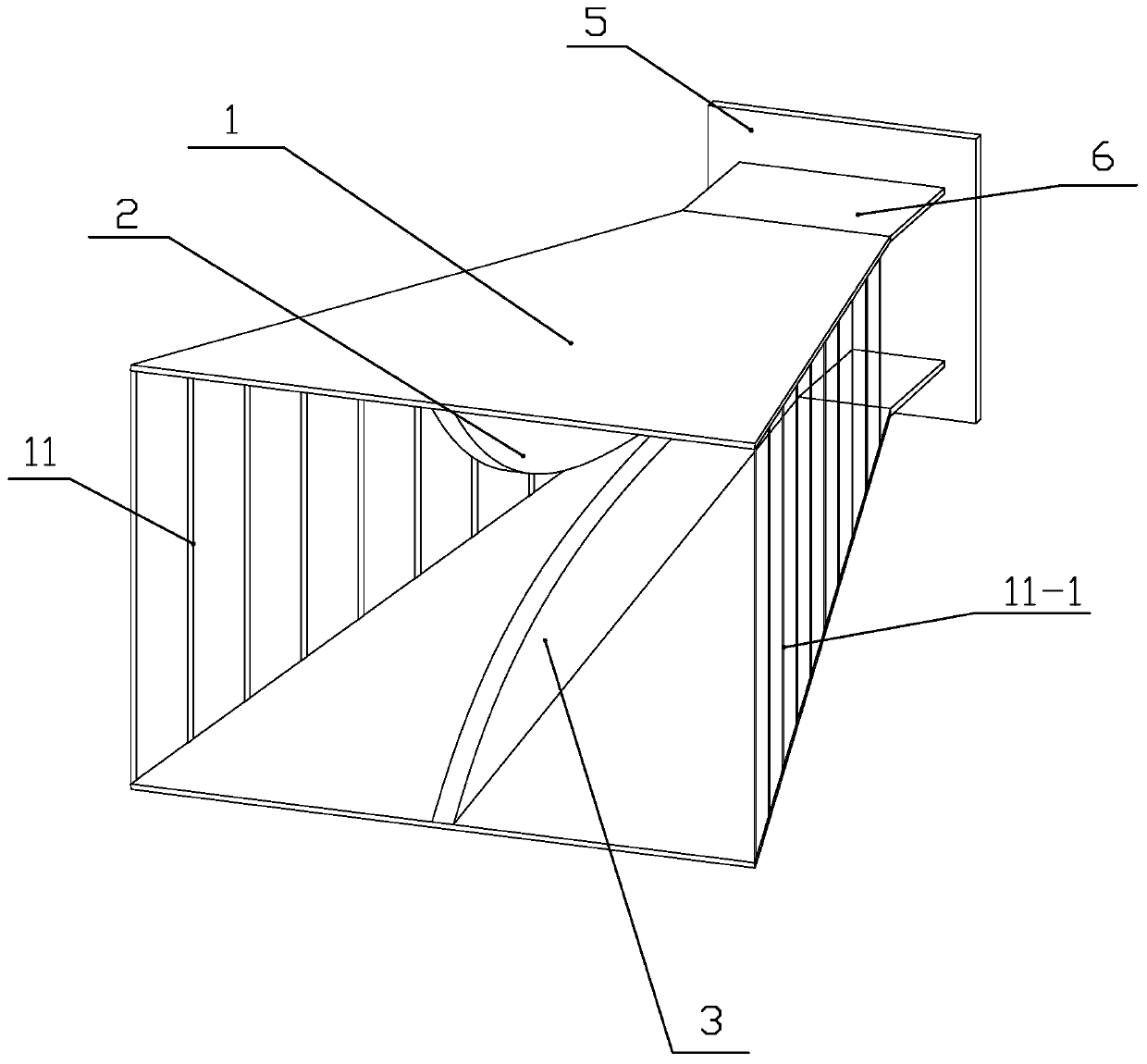
[0034] Specific implementation mode 1: Combination Figure 1~7 To illustrate this embodiment, an ultra-wideband dual-ridged horn antenna for the 1-40 GHz frequency band includes a ridged horn and a feed structure. The ridged horn includes a housing 1, an upper ridge 2 and a lower ridge 3. The casing 1 has a rectangular cone structure, and its left and right side walls are both metal grids 11. The upper ridge 2 and the lower ridge 3 are respectively fixed on the inner side of the upper and lower side walls of the casing 1, and The upper ridge 2 and the lower ridge 3 are arranged symmetrically up and down, and the ridge line of the upper ridge 2 and the ridge line of the lower ridge 3 are both curved;

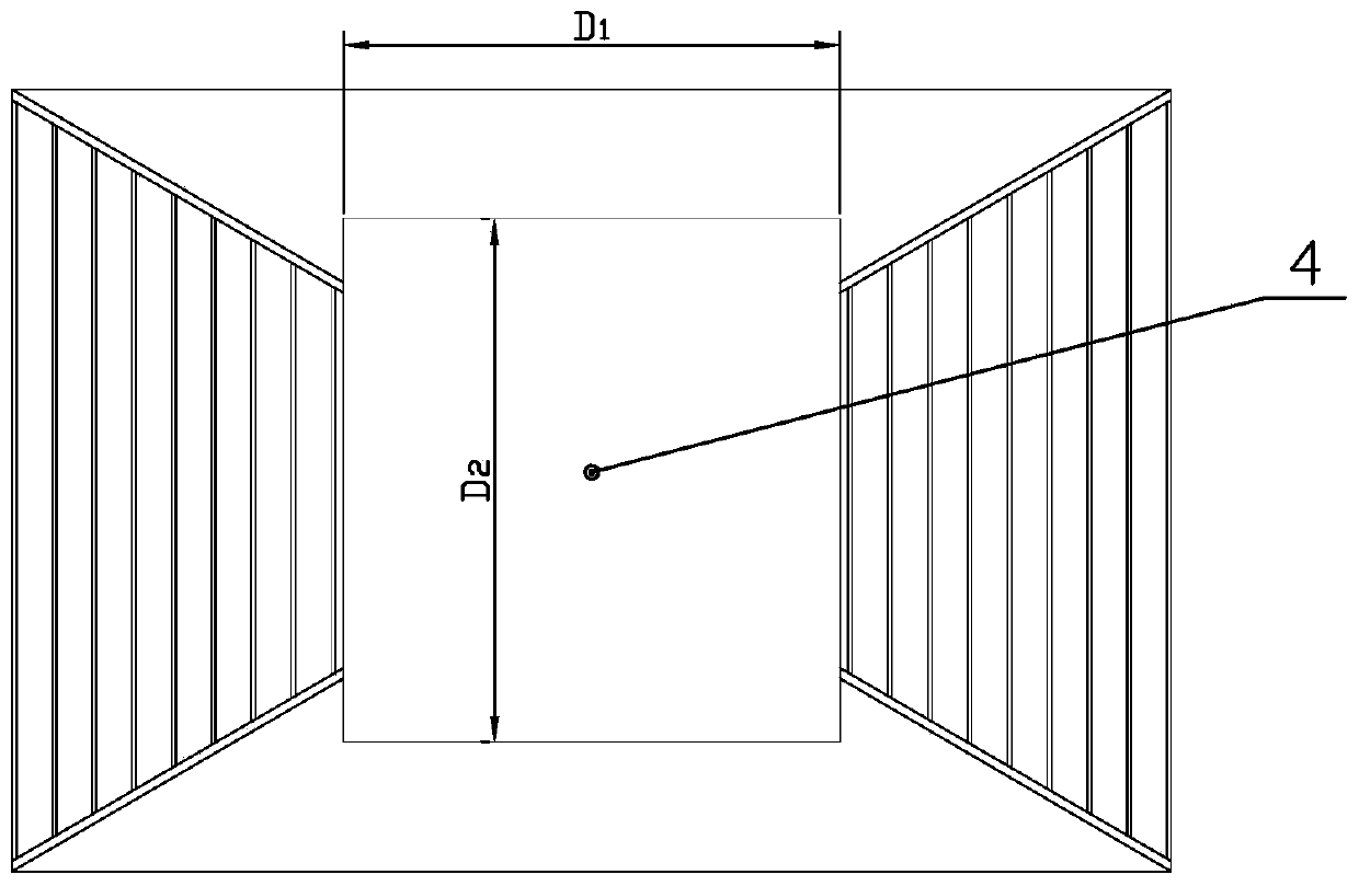
[0035] The feed structure includes a coaxial line 4, a metal floor 5, and a waveguide section 6. The metal floor 5 is arranged vertically, the coaxial line 4 is arranged horizontally, and the coaxial line 4 and the ridged horn pass through the metal floor. 5 and the waveguide sectio...

specific Embodiment approach 2

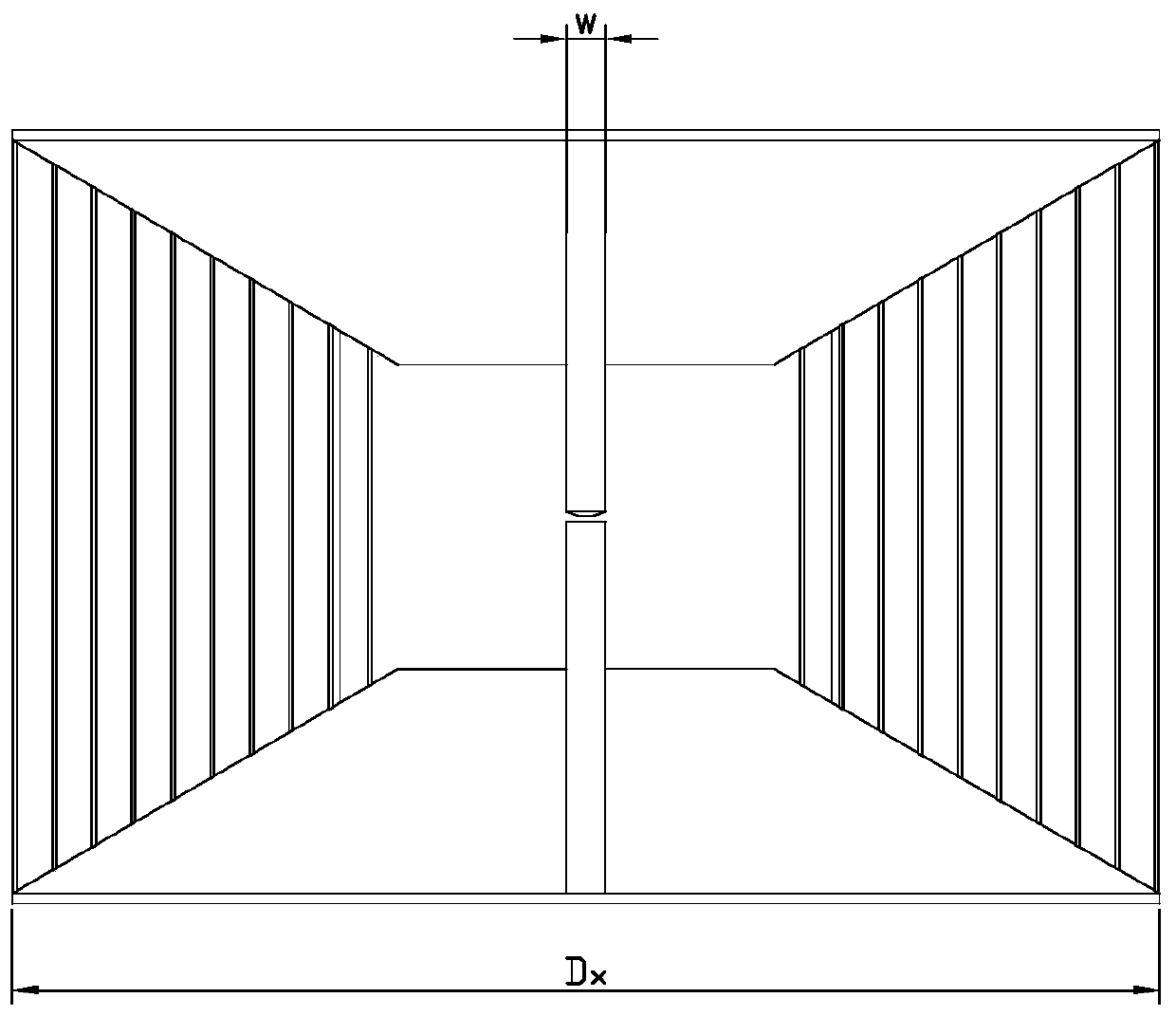
[0051] Specific implementation manner two: combination Figure 1~13 To illustrate this embodiment, the metal floor 5, the waveguide section 6 and the ridged horn are all made of aluminum. The end of the housing 1 close to the waveguide section 6 is a small end, and its width a 1 Same width as metal floor, where a 1 The value is 44-46mm. The other end of the housing 1 far from the waveguide section 6 is the large end, and its width Dx is 140mm. The upper metal transverse plate 61, the lower metal transverse plate 62, the upper side wall of the housing 1 and the housing The thickness of the lower side wall of 1 is the same, and its thickness is h 1 1.2-1.5mm, the opening angle of the upper and lower side walls of the shell 1 is determined by the ridge line and the length L of the shell 1 0 Decide where L 0 It is 205mm.

[0052] The ridge width w is 4.0-5.0mm, and the height of the end of the ridge close to the waveguide section 6 is h 3 It is 18-20mm, and the ridge line adopts the fo...


PUM


Abstract

The invention discloses an ultra-wideband double-ridge horn antenna for a 1-40GHz frequency band, and belongs to the technical field of antennas. The problems are solved that an existing double-ridgehorn antenna is poor in low-frequency-band matching performance, high-frequency-band directional diagram main lobes are split, and gain is reduced. The antenna comprises a ridged horn and a feed structure, the ridged horn comprises a shell, an upper ridge and a lower ridge, the shell is a rectangular cone structure, metal grids are arranged on the left side wall and the right side wall of the shell, the upper ridge and the lower ridge are fixedly arranged on the inner sides of the upper side wall and the lower side wall of the shell respectively, and the ridge line of the upper ridge and the ridge line of the lower ridge are curves; the feed structure comprises a coaxial line, a metal floor and a waveguide section, the metal floor is vertically arranged, the coaxial line is horizontally arranged, and the coaxial line is connected with the ridged horn through the metal floor and the waveguide section.

Description

Technical field [0001] The invention relates to an ultra-wideband double-ridged horn antenna used in the frequency band of 1-40 GHz, and belongs to the technical field of antennas. Background technique [0002] The ridged horn antenna is a typical form of ultra-wideband antenna. It has the advantages of a horn antenna such as high gain and stable radiation aperture position, and it also has an extremely wide working frequency band and a relatively small size. Therefore, ridged horn antennas have been widely used in microwave measurement and electromagnetic compatibility testing. [0003] The main problems of the existing ultra-wideband double-ridged horn antenna are: the pattern splitting gain at high frequency is reduced, the matching performance at low frequency is poor, and the feeding structure is complicated. [0004] The invention patent application with application number 201610068745.0 discloses a broadband double-ridged horn antenna. According to its specification, the ante...

Claims


Application Information

Patent Timeline
Patent Type & Authority Applications(China)
IPC IPC(8): H01Q1/48H01Q1/50H01Q13/02
CPCH01Q1/48H01Q1/50H01Q13/0275
Inventor 林澍刘首岚聂秋月张仲麟
Owner HARBIN INST OF TECH
Why Eureka
Try Eureka