Wireless charging transmitting device, wireless charging receiving device, wireless charging system, and resonance parameter matching method

A wireless charging and transmitting device technology, applied in circuit devices, battery circuit devices, current collectors, etc., can solve the problems of low charging efficiency and low wireless charging charging power, so as to improve charging efficiency, improve charging power and efficiency, reduce Effects of small voltage stress and current stress

Pending Publication Date: 2019-12-20
CHENGDU TIANFU NEW DISTRICT KUANG CHI FUTURE TECH INST
View PDF8 Cites 12 Cited by
  • Summary
  • Abstract
  • Description
  • Claims
  • Application Information

AI Technical Summary

Problems solved by technology

However, when these four types of simple topologies are used, affected by the magnetic flux leakage and coupling coefficient of the electromagnetic coupling in the topology, the current and voltage stress of the inverter device and the resonant device are relatively large, so that the charging power of wireless charging is small and the charging efficiency is low. Low

Method used


Image

  • Wireless charging transmitting device, wireless charging receiving device, wireless charging system, and resonance parameter matching method
  • Wireless charging transmitting device, wireless charging receiving device, wireless charging system, and resonance parameter matching method
  • Wireless charging transmitting device, wireless charging receiving device, wireless charging system, and resonance parameter matching method

Examples


Embodiment 1

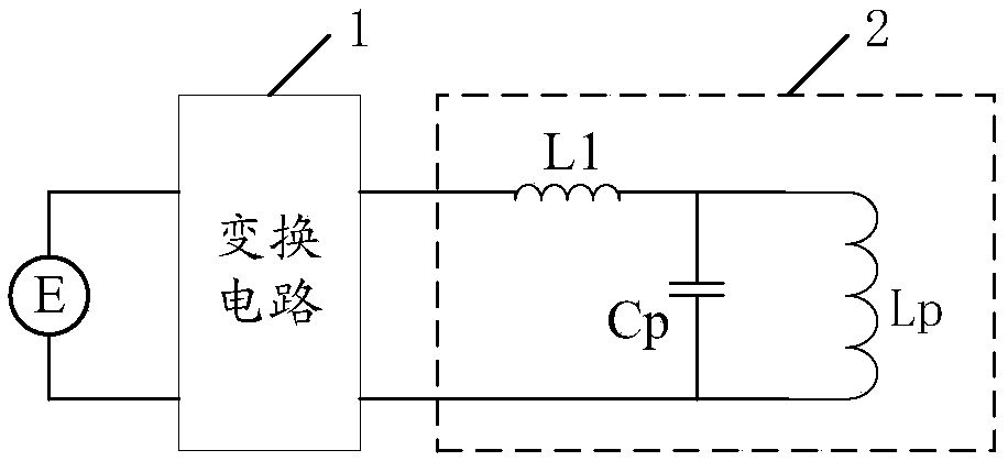
[0036] Please refer to figure 1 , figure 1 A schematic structural diagram of a wireless charging transmitting device provided by an embodiment of the present invention, as shown in figure 1 As shown, the wireless charging transmitting device is applied to the transmitting end, including a conversion circuit 1 and a primary side resonant circuit 2 connected to the output end of the conversion circuit 1; wherein, the conversion circuit 1 is used to generate high-frequency alternating current, which can convert the power supply E The provided direct current is converted into high-frequency alternating current, and the high-frequency alternating current is output through two output terminals; the primary side resonant circuit 2 includes a first compensation inductance L1, a primary coil Lp and a first resonant capacitor Cp, the first resonant capacitor Cp and a primary The coil Lp is connected in parallel to the two output terminals of the conversion circuit 1, and is used to gen...

Embodiment 2

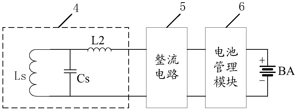
[0041] Please refer to image 3 , image 3 A schematic structural diagram of a wireless charging receiving device provided by an embodiment of the present invention, as shown in image 3 As shown, the wireless charging receiving device is applied to the receiving end, including a secondary resonant circuit 4, a rectifier circuit 5 and a battery management module 6. The secondary resonant circuit 4 generates alternating current through magnetic field inductive coupling with the wireless charging transmitting device, and the The alternating current is input to the rectification circuit 5 , and the rectification circuit 5 rectifies the alternating current into direct current, and then inputs the direct current to the battery management module 6 to charge the battery BA through the battery management module 6 . Specifically, the secondary side resonant circuit 4 includes a secondary coil Ls, a second resonant capacitor Cs, and a second compensation inductance L2, the secondary co...

Embodiment 3

[0047] This embodiment provides a wireless charging system, including the wireless charging transmitting device described in Embodiment 1 and the wireless charging receiving device described in Embodiment 2. Specifically, see Figure 5 The wireless charging system provided in this embodiment includes a conversion circuit 1, a primary side resonant circuit 2, a secondary side resonant circuit 4, a rectifier circuit 5 and a battery management module 6, the conversion circuit 1 and the primary side resonant circuit 2 form a transmitting end, and the secondary side The resonant circuit 4 , the rectifier circuit 5 and the battery management module 6 form a receiving end, and the transmitting end and the receiving end transmit electric energy through magnetic field induction coupling. When the system is working, the conversion circuit 1 at the transmitting end converts the DC power provided by the power supply E into a high-frequency AC power, and outputs the generated high-frequenc...


PUM


Abstract

A wireless charging transmitting device, a wireless charging receiving device, a wireless charging system, and a resonance parameter matching method are provided. The system includes: a conversion circuit for generating high-frequency alternating current; a primary-side resonance circuit including a resonance capacitor Cp, a primary coil Lp, and a compensation inductor L1, wherein the Cp and the Lp are connected in parallel between the two output ends of the conversion circuit and are for generating an alternating electromagnetic field through resonance, and the L1 is connected between a parallel node of the Cp and the Lp and the conversion circuit; a secondary-side resonance circuit including a secondary coil Ls, a resonance capacitor Cs and a compensation inductor L2, wherein the Ls andthe Cs are connected in parallel and are used for generating alternating current through magnetic field inductive coupling, one end of the L2 is connected to a parallel node of the Ls and the Cs, andthe other end of the L2 and the other parallel node of the Ls and the Cs are used as two output ends to output alternating current; and a rectifier circuit and a battery management module which are successively connected to the secondary-side resonance circuit. The L1 and the L2 can reduce the voltage and current stress of an inverter device and a resonant device, provides a device with greater power at the same current, and improves the charging power and efficiency when the battery is wirelessly charged.

Description

technical field [0001] The present invention relates to the technical field of wireless power transmission, in particular to a wireless charging transmitting device, receiving device, system and resonance parameter matching method. Background technique [0002] In products such as drones, electric vehicles, robots, and household appliances, rechargeable batteries are usually used to provide energy, and wired chargers are commonly used when charging the batteries. For example, for unmanned aerial vehicles, it uses lithium batteries to provide energy. Due to the particularity of the unmanned aerial vehicle itself, it requires light weight and limited space. Lithium battery is charged. However, in some special application scenarios, or for products with special needs, using a wired charger to charge the battery may have problems such as poor contact, overheating and burning, which limits the charging demand of the battery. With the advancement of science and technology, wirel...

Claims


Application Information

Patent Timeline
Patent Type & Authority Applications(China)
IPC IPC(8): H02J50/12H02J7/00
CPCH02J50/12
Inventor 刘若鹏栾琳罗密
Owner CHENGDU TIANFU NEW DISTRICT KUANG CHI FUTURE TECH INST
Why Eureka
Try Eureka