
In-situ chemical reactor and combined system of in-situ chemical reactor and nuclear magnetic resonance

A chemical reactor and nuclear magnetic resonance technology, which is applied in the fields of nuclear magnetic resonance analysis, scientific instruments, instruments, etc., can solve problems affecting Xe nuclear magnetic shielding, electron cloud density, and chemical shift

Pending Publication Date: 2019-12-24
DALIAN INST OF CHEM PHYSICS CHINESE ACAD OF SCI
View PDF0 Cites 1 Cited by
  • Summary
  • Abstract
  • Description
  • Claims
  • Application Information

AI Technical Summary

Problems solved by technology

Since it does not react chemically with other substances, it is very easy to act on the inner and outer surfaces of the substance when it comes into contact with it, thus affecting 129 The electron cloud density of Xe, which in turn affects the magnetic shielding of the Xe nucleus and affects its chemical shift

Method used


Image

  • In-situ chemical reactor and combined system of in-situ chemical reactor and nuclear magnetic resonance
  • In-situ chemical reactor and combined system of in-situ chemical reactor and nuclear magnetic resonance
  • In-situ chemical reactor and combined system of in-situ chemical reactor and nuclear magnetic resonance

Examples


Embodiment 1

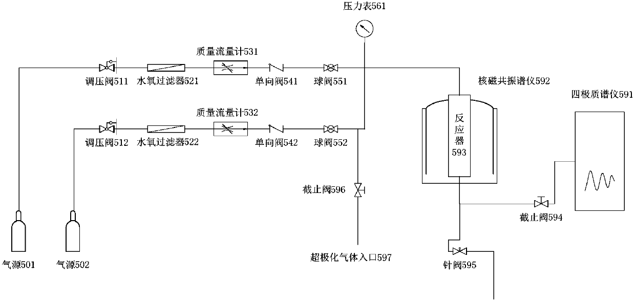
[0053] A form of realization of the in-situ chemical reactor of the present invention is as follows: Figure 3A with Figure 3B as shown, Figure 3A is the structural diagram of the gas-solid phase reactor (reactor A), Figure 3B It is an exploded view of the composition of the gas-solid phase reactor (reactor A).

[0054] The reactor is a closed straight tube type. The bottom end of the outer tube 601 of the reactor is closed, the top end is open, and the top end has threads. The top end seals the outer tube 601 through a sealing rod 612. The sealing rod 612 is equipped with a rubber sealing O-ring 613, and the sealing rod 612 is sealed together with the outer tube 601 through the fixing bolt 611 of the sealing rod. The sealing rod 612 is equipped with gas inlet and outlet pipelines. The reactor is a nested structure of an inner tube and an outer tube. The gas enters the upper part of the sample through the inner tube, flows out from the bottom after flowing through the s...

Embodiment 2

[0061] Another realization of the above-mentioned chemical reactor is a gas-liquid chemical reactor (reactor B), in which liquid reactants are filled into the outer tube, and its basic structure is similar to that of reactor A, the difference is that the length or shape of the inner tube of the sample tube is different , the reactor is suitable for studying the multiphase chemical reaction system of liquid and gas.

[0062] attached Figure 5A and 5B The structure diagrams of two different gas-liquid reactors are respectively: attached Figure 5A In the reactor shown, the inner tube is 30-40 mm shorter than the inner tube of reactor A. When filling liquid reactants, the bottom end of the inner tube (ie, the gas outlet) is close to the liquid surface of the liquid reactant in the outer tube but does not touch the liquid surface. , such a design makes the flowing gas have less influence on the liquid, and the liquid will not be blown and bubbling by the gas, which basically ha...

Embodiment 3

[0065] This example utilizes hyperpolarized 129 Xe probes are used to study the pore structure changes in porous materials with MFI structure. Using the reactor described in Example 1, the measured substance records the MFI structure material of each different structure at different temperatures 129 Xe NMR spectrum.

[0066] 1. Experimental method


PUM


Abstract

The invention relates to a device for researching a chemical reaction process in situ. The chemical reaction device is suitable for operation in high-temperature and low-temperature conditions, can provide a chemical reaction process and nuclear magnetic resonance information of a physical structure by being combined with a nuclear magnetic resonance technology, can provide reaction product information, such as quadrupole mass spectrometry and can also achieve dynamic research on millisecond time-resolution reaction. The device is suitable for nuclear magnetic resonance research in the fieldsof chemistry and materials and can also be applied to the fields, such as hyperpolarized atomic magnetic resonance imaging and magnetic resonance spectroscopy testing in the medical field.

Description

technical field [0001] The invention relates to an in-situ chemical reactor and its combined system with nuclear magnetic resonance, which is suitable for nuclear magnetic resonance research in the fields of chemistry and materials, and can also be used for hyperpolarized atom magnetic resonance imaging and magnetic resonance spectroscopy in the medical field testing and other fields. Background technique [0002] The in-situ study of chemical reaction process and material structure under chemical reaction conditions is the analytical method that most chemists strive for. Scientists try to study the chemical reaction process in situ on a variety of chemical analysis instruments in order to reveal the secrets of the chemical reaction process. The chemical reaction process has little information detail. NMR technology can give its structural information through the bulk phase test of the measured substance, and has aroused great interest because it is very suitable for study...

Claims


Application Information

Patent Timeline
IPC IPC(8): G01N24/08G01N27/62G01N30/02
CPCG01N24/08G01N27/62G01N30/02
Inventor 刘宪春韩秀文包信和
Owner DALIAN INST OF CHEM PHYSICS CHINESE ACAD OF SCI
Learn More