2-FSK (Frequency Shift Keying) wake-up receiver of tuned radio frequency architecture and demodulation method thereof
A 2-FSK, wake-up receiver technology, applied in FM carrier system, power management, electrical components, etc., to achieve the effect of simple operation, reduced power consumption, and high receiving sensitivity
- Summary
- Abstract
- Description
- Claims
- Application Information
AI Technical Summary
Problems solved by technology
Method used
Image

Examples
Embodiment 1
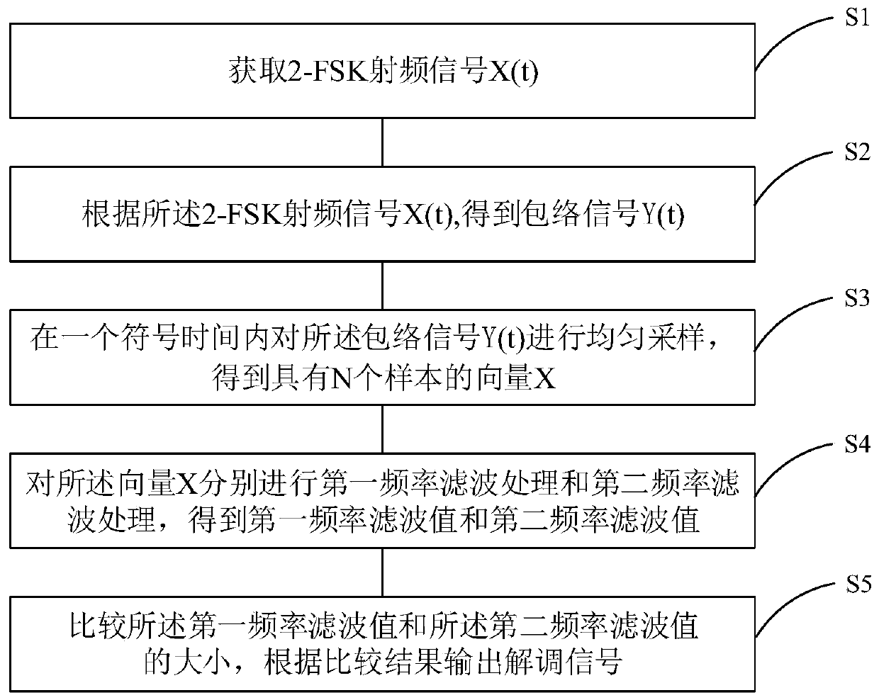
[0067] See figure 1 , figure 1 It is a flowchart of a demodulation method applied to a 2-FSK wake-up receiver of a tuned radio frequency architecture provided by an embodiment of the present invention. It is applied to a 2-FSK wake-up receiver of a tuned radio frequency architecture. As shown in the figure, the demodulation Methods include:
[0068] S1: Acquire 2-FSK radio frequency signal X(t),
[0069] X(t)=Acos(2πf RF t)cos(2πf IF t+θ), 0
[0070] Among them, A represents the amplitude of the radio frequency signal, f RF Indicates the frequency of the RF signal, f IF Represents the frequency of the intermediate frequency signal, θ represents the phase error, and T represents a symbol time;
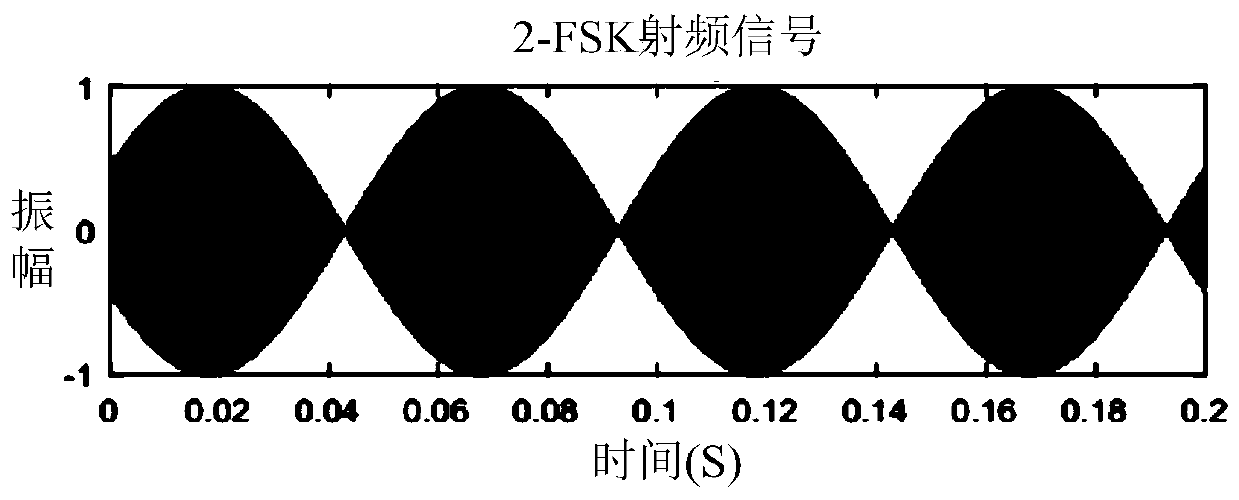
[0071] See figure 2 , figure 2 It is a schematic diagram of a 2-FSK radio frequency signal provided by the embodiment of the present invention. 2-FSK modulation, that is, binary digital frequency modulation, uses a binary digital baseband signal to control the freque...
Embodiment 2
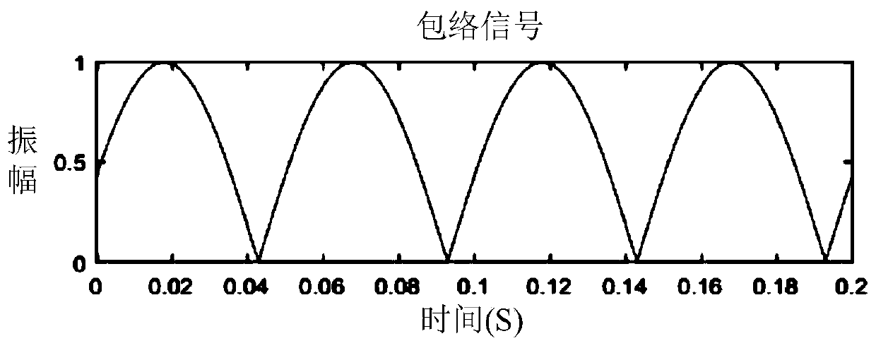
[0113] Please refer to Figure 5 , Figure 5 It is a structural block diagram of a 2-FSK wake-up receiver with a tuned radio frequency architecture provided by an embodiment of the present invention. As shown in the figure, the 2-FSK wake-up receiver of the tuned radio frequency architecture of this embodiment includes: an antenna 1, a bandpass filter 2, an envelope detector 3 and a control module 4 connected in sequence, wherein the antenna 1 is used to receive 2-FSK radio frequency signal X (t); Band-pass filter 2 is used for carrying out band-pass filter processing to described 2-FSK radio frequency signal X (t), obtains filtered signal; Envelope detector 3 is used for described filtering Envelope detection is performed on the signal to obtain an envelope signal Y(t); the control module 4 is used to sample the envelope signal Y(t) and demodulate it to obtain a demodulated signal.
[0114] Specifically, the control module 4 includes a sampling unit 41, a first frequency fi...
Embodiment 3
[0119] This embodiment is to evaluate the performance of the 2-FSK wake-up receiver of the tuned radio frequency architecture of the above embodiment. In this embodiment, the MSP430RF5969 MCU is selected as the control module, and the AD8309 power detector is used as the envelope Detector to evaluate the performance of a 2-FSK wake-up receiver tuned to the RF architecture. See Table 1 for performance parameters of the MSP430RF5969 and AD8309.
[0120] Table 1. Performance parameters of MSP430RF5969 and AD8309
[0121]
[0122] In a 2-FSK wake-up receiver with a tuned RF architecture, the first frequency filter and the second frequency filter are negligible compared to the sampling time of the ADC.
[0123] Let P D,a and P D,s is the working power and sleep power of the envelope detector, P M,a and P M,s is the working power and sleep power of the microcontroller, R is the bit rate of the receiver, T sa is the sampling conversion time of the ADC of the single-chip micr...
PUM
 Abstract
Description
Claims
Application Information
 - R&D
- Intellectual Property
- Life Sciences
- Materials
- Tech Scout
- Unparalleled Data Quality
- Higher Quality Content
- 60% Fewer Hallucinations
Browse by: Latest US Patents, China's latest patents, Technical Efficacy Thesaurus, Application Domain, Technology Topic, Popular Technical Reports.
© 2025 PatSnap. All rights reserved.Legal|Privacy policy|Modern Slavery Act Transparency Statement|Sitemap|About US| Contact US: help@patsnap.com