
Full-automatic steel tapping method and system of converter

A tapping system and fully automatic technology, which is applied in steel manufacturing process, manufacturing converter, climate sustainability, etc., can solve the problem of long time for slag layer to pass through the tapping hole, large change of molten steel static pressure, and tapping time. Fluctuation and other problems, to achieve the effect of reducing the incidence of abnormal production, reducing investment, and reducing labor intensity

Inactive Publication Date: 2019-12-27
BAOSHAN IRON & STEEL CO LTD
View PDF4 Cites 20 Cited by
  • Summary
  • Abstract
  • Description
  • Claims
  • Application Information

AI Technical Summary

Problems solved by technology

[0012] (1) Since the shaking furnace is operated by workers, the operating strength and angle are completely controlled manually. Therefore, the situation that the shaking furnace is too strong may cause slag overflow at the furnace mouth, or the shaking furnace is too slow to cause the slag layer to pass through the tap hole. Long, the amount of slag is large; and for the angle of the shaking furnace, due to the artificial control of the angle, there will be a large change in the static pressure of the molten steel during tapping, and there will be obvious fluctuations in the tapping time;
[0013] (2) Since the position of the mobile ladle trolley is judged by manual observation and experience in step 2, there may be a phenomenon of molten steel overflow due to improper operation
However, the tapping process of the converter automatic tapping control method is not controlled by a mathematical model

Method used


Image

  • Full-automatic steel tapping method and system of converter
  • Full-automatic steel tapping method and system of converter
  • Full-automatic steel tapping method and system of converter

Examples


Embodiment Construction

[0072] The method and system for fully automatic tapping of converters described in the present invention will be further explained and described below in conjunction with the accompanying drawings and specific embodiments of the present invention. However, the explanation and description do not constitute improper limitations on the technical solution of the present invention.

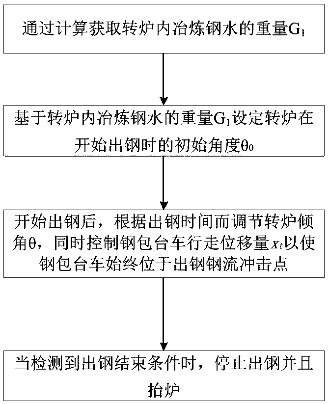
[0073] figure 1 It is a schematic flow chart of an embodiment of the fully automatic tapping method for a converter according to the present invention.

[0074] like figure 1 As shown, in this embodiment, the fully automatic tapping method of the converter includes the following steps:

[0075] (1) Obtain the weight G of molten steel smelted in the converter by calculation 1 ;

[0076] (2) Based on the weight G of molten steel smelted in the converter 1 Set the initial angle θ of the converter at the beginning of tapping 0 ;

[0077] (3) After the steel tapping starts, adjust the inclination ang...


PUM


Abstract

The invention discloses a full-automatic steel tapping method of a converter. The method comprises the steps of (1) obtaining the weight G1 of smelting molten steel in the converter through calculation; (2) based on the weight G1 of the smelting molten steel in the converter, setting the initial angle theta 0 when steel tapping of the converter begins; (3) after steel tapping begins, adjusting theinclination angle theta of the converter according to the steel tapping time, and meanwhile, controlling the walking displacement xt of a steel ladle trolley, so that the steel ladle trolley is located at a steel tapping steel flow impact point all the time; (4) when a steel tapping end condition is detected, stopping steel tapping and lifting up the converter. The invention further discloses a full-automatic steel tapping system of the converter. The system comprises the converter, the steel ladle trolley, a second-level microcomputer system storing steel grade smelting information, a converter inclination angle measurement device for measuring the inclination angle of the converter, a converter tilting driving device connected with the converter, a steel ladle trolley position detectiondevice for detecting the position of the steel ladle trolley in the walking direction, a steel ladle trolley walking driving device connected with the steel ladle trolley, a slag discharging device and a control system.

Description

technical field [0001] The invention relates to a method and system for automatic steelmaking in a converter, in particular to a method and system for fully automatic steel tapping in a converter. Background technique [0002] At present, major steel mills around the world basically have converter automatic smelting, which can effectively improve the success rate of smelting, shorten the smelting cycle, improve output and quality, reduce raw material consumption and cost, and greatly reduce the labor intensity of workers. However, although the automatic steelmaking of the converter has been relatively popular in the prior art, the tapping of the converter is generally carried out manually. [0003] Usually converter tapping includes the following steps: [0004] 1) Determine that the composition and temperature of the molten steel end point meet the tapping requirements; [0005] 2) After driving the ladle car to the position of accepting molten steel; [0006] 3) The sha...

Claims


Application Information

Patent Timeline
Patent Type & Authority Applications(China)
IPC IPC(8): C21C5/28C21C5/46
CPCC21C5/28C21C5/46C21C2300/06Y02P10/25
Inventor 于艳蒋晓放赵晓波李火中朱峰
Owner BAOSHAN IRON & STEEL CO LTD
Learn More