Sand core used for sand casting and preparing method thereof

A sand casting and sand core technology, which is applied in the field of hollow sand core preparation of sand casting, can solve the problems of large air volume of the sand core and difficulty in sand falling, and achieve the effects of reducing casting costs, improving quality, and reducing the amount of sand used

Pending Publication Date: 2019-12-31
北京瑞泓翔宏大科技发展有限公司
View PDF0 Cites 5 Cited by
  • Summary
  • Abstract
  • Description
  • Claims
  • Application Information

AI Technical Summary

Problems solved by technology

[0005] The present invention aims to overcome the problems of large amount of gas generated by the sand core and difficult sand falling in the prior art, and provides a hollow sand core for sand casting

Method used


Image

  • Sand core used for sand casting and preparing method thereof
  • Sand core used for sand casting and preparing method thereof
  • Sand core used for sand casting and preparing method thereof

Examples


preparation example Construction

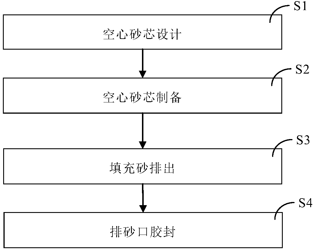
[0041] Such as figure 1 Shown, the preparation method of the sand core of the present embodiment comprises the following steps:

[0042] S21. Design of sand core 1: according to the shape of sand core 1, design a three-dimensional model of sand core 1 through modeling software. A sand discharge piston 4 is provided at the sand port 3, and a vent hole 5 is provided on the sand discharge piston 4;

[0043] S2. Sand core 1 preparation: use 3DP resin sand to prepare sand core 1 and sand discharge piston 4 through 3DP printing equipment;

[0044] S3. Filling sand discharge: discharge the dry sand in the cavity 2 through the sand discharge port 3;

[0045] S4. Rubber sealing of the sand discharge port 3: the sand discharge piston 4 is sealed to the sand discharge port 3 with heat-resistant glue.

Embodiment 2

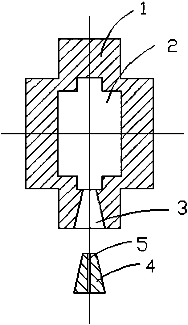
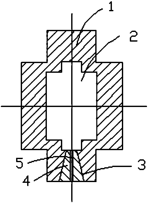
[0047] Such as Figure 4~6 As shown, the present embodiment provides a sand core for sand casting, which includes a sand core 1, a cavity 2 is provided inside the sand core 1, and the sand core 1 is provided with at least one sand outlet 3, so as to figure 2 In the shown embodiment, three sand discharge ports 3 are provided, and a sand discharge piston 4 for blocking the sand discharge ports 3 is provided at the sand discharge ports 3 . In order to ensure that the shape is consistent after plugging, a stop 31 with a large outside and a small inside is provided at the sand discharge port 3, and a boss matching the stop 31 is provided on the end face of the sand discharge piston 4, so that the sand discharge piston 4 is covered to the sand discharge. At the mouth, the outer end face of the sand discharge piston 4 is flush with the end face of the sand discharge port 3. The sand discharge piston 4 is provided with an exhaust hole 5 .

[0048] see Figure 4 , the section of th...

Embodiment 3

[0054] Example 3, see Figure 8 , is a cross-sectional view of a hollow sand core for sand casting. The difference from the previous embodiment is that the hollow grid shape is an equilateral triangle.

[0055] The preparation method of the hollow sand core for sand casting is the same as the method in Example 1. After the filling sand in the grid is emptied, the sand discharge piston is used to block the sand discharge port with heat-resistant glue.


PUM


Abstract

The invention discloses a sand core used for sand casting and a preparing method thereof. The method comprises the following steps of S1, sand core (1) design; S2, sand core (1) preparing; S3, fillersand discharging and S4, glue sealing of a sand discharging opening (3). A cavity (2) is formed in the sand core (1), the sand discharging opening (3) is formed in one end of the sand core (1), a sanddischarging piston (4) is arranged on the sand discharging opening (3), and an exhaust hole (5) is formed in the sand discharging piston (4). According to the preparing method of the sand core used for sand casting, the use amount of moulding sand and resin can be greatly reduced, the resin gas volume is reduced, the decoring and sand shakeout efficiency can be improved, the regeneration efficiency of a used sand machine is improved, resource consumption, waste discharge and cost are reduced, production efficiency of the casting can be improved, and the feasible technology and method of greencasting is achieved.

Description

technical field [0001] The invention relates to the field of sand casting, in particular to a method for preparing a hollow sand core for sand casting. Background technique [0002] The casting method of the casting in the inner cavity mostly adopts the sand core process, and the metal inner cavity is formed by sanding out and removing the core after pouring and solidification. The traditional sand core preparation uses silica sand, ceramsite sand, chromite sand, and olivine sand as the main materials, which are solidified and formed through the chemical reaction of binder and curing agent. Most of the traditional casting processes use core box molds. Sand shooting or artificial sand filling is completed, and the curing process is divided into heat curing and cold curing. The sand core preparation technology proposed in this patent is prepared through the self-hardening of chemical binders on a 3DP sand printer. [0003] The following problems exist in the existing large-s...

Claims


Application Information

Patent Timeline
IPC IPC(8): B22C9/10B33Y10/00B33Y80/00
CPCB22C9/10B33Y10/00B33Y80/00
Inventor 于彦奇
Owner 北京瑞泓翔宏大科技发展有限公司
Why Eureka
Try Eureka