Sensing prob as well as fiber interfering device and method for inhibiting polarization-induced fading
A sensing probe and optical fiber technology, which is applied to measurement devices, instruments, and the use of wave/particle radiation, etc., can solve the problems of random fading of detection signals, reduce the signal-to-noise ratio of the system, increase the system cost, etc., to suppress the birefringence effect and The effect of polarization fluctuation, accurate detection of acoustic signal, and stable interference signal
- Summary
- Abstract
- Description
- Claims
- Application Information
AI Technical Summary
Problems solved by technology
Method used
Image

Examples
Embodiment 1
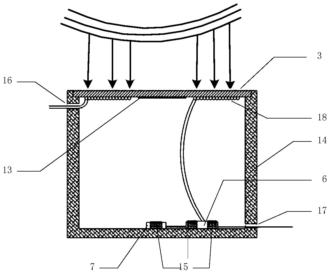
[0047] Such as figure 1 As shown, the present embodiment provides a sensing probe, which includes:
[0048]Sealed chamber 12, the sealed chamber 12 is provided with a sensing diaphragm 3, a first circulator 6 and a first Faraday rotating mirror 7; the sensing diaphragm 3 is used to sense external acoustic vibration signals; the sensing diaphragm 3 is also provided with There is a boss 13 to increase the sensitivity of the sensing probe; the sensing diaphragm 3 is provided with a sensing fiber ring 18, one end of the sensing fiber ring 18 is connected to the input optical fiber, and the other end is connected to the first port d of the first circulator 6 The second port e of the first circulator 6 is connected to the first Faraday mirror 7; the third port f of the first circulator 6 outputs the detection light for sensing the change of the external sound wave vibration signal.
Embodiment approach
[0049] As an implementation manner, the sensing diaphragm adopts a circular elastic diaphragm.
[0050] For example: the Young's modulus of a circular elastic diaphragm is 10GPa, the Poisson's ratio is 0.3, the radius is 50mm, and the thickness is 1mm.
[0051] The advantage of the above technical solution is that this embodiment uses a circular elastic diaphragm to detect the acoustic vibration signal, so that only the pressure deformation in the center of the circular elastic diaphragm can be detected, which can be deformed under a weak acoustic signal, and thus make The sensing optical fiber ring pasted on the elastic diaphragm generates strain to improve the accuracy of acoustic signal detection.
[0052] As an implementation manner, the boss is a circular boss, and the circular boss coincides with the center of the circular elastic diaphragm.
[0053] In this embodiment, the materials of the sensing diaphragm and the boss are the same, and both are made of organic polyme...
Embodiment 2
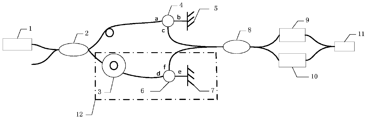
[0071] Such as figure 2 As shown, a kind of optical fiber interference device for suppressing polarization fading of the present embodiment includes:
[0072] Laser 1, the optical signal output by it is divided into two beams of light by the first coupler 2, and enters the sensing arm optical fiber and the reference arm optical fiber respectively; figure 1 The sensing probe shown is connected, wherein the sensing arm fiber is an input fiber; the reference arm fiber is connected to the first port a of the second optical circulator 4, and the second port b of the second optical circulator 4 is connected to the first port a of the second optical circulator 4 The two Faraday mirrors are connected; the third port c of the second optical circulator 4 outputs the reference light;
[0073] Both the third port f of the first optical circulator 6 and the third port c of the second circulator 4 are connected to the second coupler 8, and in the second coupler 8, the detection light inte...
PUM
| Property | Measurement | Unit |
|---|---|---|
| Young's modulus | aaaaa | aaaaa |
| Radius | aaaaa | aaaaa |
| Thickness | aaaaa | aaaaa |
Abstract
Description
Claims
Application Information
 - Generate Ideas
- Intellectual Property
- Life Sciences
- Materials
- Tech Scout
- Unparalleled Data Quality
- Higher Quality Content
- 60% Fewer Hallucinations
Browse by: Latest US Patents, China's latest patents, Technical Efficacy Thesaurus, Application Domain, Technology Topic, Popular Technical Reports.
© 2025 PatSnap. All rights reserved.Legal|Privacy policy|Modern Slavery Act Transparency Statement|Sitemap|About US| Contact US: help@patsnap.com