
Optical fiber coupling system and coupling method

An optical fiber coupling and coupling mirror technology, which is applied in the optical fiber coupling system and coupling field, can solve the problems of low coupling alignment accuracy, atmospheric turbulence interference, and small effective working range, and achieves a large effective field of view, strong anti-interference ability, and suitable for wide range of effects

Active Publication Date: 2019-12-31
CHANGCHUN INST OF OPTICS FINE MECHANICS & PHYSICS CHINESE ACAD OF SCI
View PDF5 Cites 7 Cited by
  • Summary
  • Abstract
  • Description
  • Claims
  • Application Information

AI Technical Summary

Problems solved by technology

[0008] In order to solve the problems that the existing optical fiber coupling system has a small effective working range, low coupling alignment accuracy, and serious interference by atmospheric turbulence, the present invention provides an optical fiber coupling system and a coupling method

Method used


Image

  • Optical fiber coupling system and coupling method
  • Optical fiber coupling system and coupling method
  • Optical fiber coupling system and coupling method

Examples


Embodiment Construction

[0026] The present invention will be further described in detail below in conjunction with the drawings and embodiments.

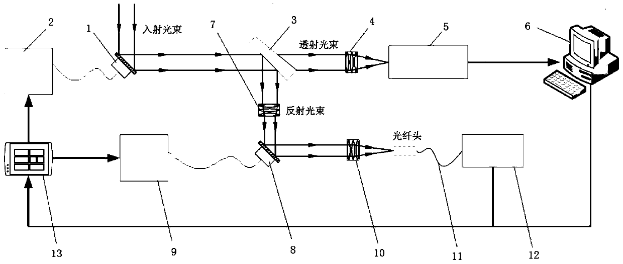
[0027] A fiber coupling system, including spot tracking quick mirror 1, tracking mirror driver 2, beam splitter 3, imaging lens group 4, spot position detector 5, image processor 6, nutation coupling quick mirror 8, coupling mirror driver 9. Coupling lens group 10, coupling fiber 11, light energy detector 12 and controller 13, such as figure 1 .

[0028] The spot position detector 5 is placed on the focal plane of the imaging lens group 4. The end face of the fiber tip of the coupling fiber 11 is placed on the focal plane of the coupling lens group 10, and the optical axis of the fiber tip and the optical axis of the coupling lens group 10 are coaxial. The tracking mirror driver 2 is connected to and drives the light spot to track the fast mirror 1 to move, and the light spot position detector 5 is connected to the image processor 6. The coupling mirror drive...


PUM


Abstract

The invention discloses an optical fiber coupling system and a coupling method, relates to the technical field of optical fiber coupling, and solves the problems that the effective working range is small, the coupling alignment precision is low, and the interference of atmospheric turbulence is serious. The optical fiber coupling system comprises a light spot tracking fast steering mirror, a tracking mirror driver, a beam splitter, an imaging lens group, a light spot position detector, an image processor, a nutation coupling fast steering mirror, a coupling mirror driver, a coupling lens group, a coupling optical fiber, a light energy detector and a controller, wherein the light spot position detector is placed on a focal plane of the imaging lens group, the end face of an optical fiber head of the coupling optical fiber is placed on a focal plane of the coupling lens group, and the optical axis of the optical fiber head is coaxial with the optical axis of the coupling lens group. According to the invention, optical fiber coupling with large effective view field, strong anti-interference capability and high coupling efficiency is realized. The optical fiber coupling efficiency canstill be kept under the influence of atmospheric turbulence, the overall communication quality of a laser communication link is guaranteed, and the application range is wide.

Description

Technical field [0001] The invention relates to the technical field of optical fiber coupling, in particular to an optical fiber coupling system and a coupling method. Background technique [0002] Efficient and stable space light-single-mode fiber coupling technology is the prerequisite and guarantee for the realization of high-speed and long-distance laser communication technology, and it is also a key technology in space laser application systems such as lidar and optoelectronic countermeasures. Due to optical machining, assembly adjustment, vibration and other reasons, the coupled beam will have tilt, defocus or other aberrations, resulting in a significant drop in the coupling efficiency of the spatial light-single-mode fiber. [0003] When the fiber coupling technology is applied in the atmospheric environment, the turbulence effect of the atmosphere causes serious interference to the laser beam when the laser beam propagates in the atmosphere, which makes the beam arrival an...

Claims


Application Information

Patent Timeline
Patent Type & Authority Applications(China)
IPC IPC(8): G02B6/42
CPCG02B6/4204G02B6/4214G02B6/4225
Inventor 刘永凯王建立董全睿张健强高世杰盛磊陈云善
Owner CHANGCHUN INST OF OPTICS FINE MECHANICS & PHYSICS CHINESE ACAD OF SCI
Learn More