On-machine measuring device and measuring method applicable to energetic rotating parts

A technology for measuring devices and rotating parts, applied in mechanical measuring devices, measuring devices, mechanical diameter measurement, etc., can solve problems such as lack of technical scalability, difficulty in automatic realization, difficulty in multi-feature centralized measurement, etc., to achieve the improvement of essential safety The effect of level, low cost and functional integration

Pending Publication Date: 2020-01-03
INST OF CHEM MATERIAL CHINA ACADEMY OF ENG PHYSICS
View PDF5 Cites 0 Cited by
  • Summary
  • Abstract
  • Description
  • Claims
  • Application Information

AI Technical Summary

Problems solved by technology

[0004] In a comprehensive view, the existing technologies and invention reports still have the following deficiencies in solving the problem of on-site measurement in the automatic processing of energetic materials: 1) The on-machine probe method must rely on the feeding accuracy of the numerical control system, and there are high problems in data acquisition and analysis. Technical difficulty is not conducive to automatic realization; 2) Special measuring tools for designated features and comparison model method are difficult to realize multi-feature centralized measurement, and the requirements for tooling structure design and manufacturing precision are very high, and it is difficult to realize automation by relying on operator experience; 3) Most inventions Aiming at the application in this field, lack of technical expansion, the surface quality of energetic components is difficult to meet the requirements of non-contact measurement

Method used


Image

  • On-machine measuring device and measuring method applicable to energetic rotating parts
  • On-machine measuring device and measuring method applicable to energetic rotating parts
  • On-machine measuring device and measuring method applicable to energetic rotating parts

Examples


Embodiment 1

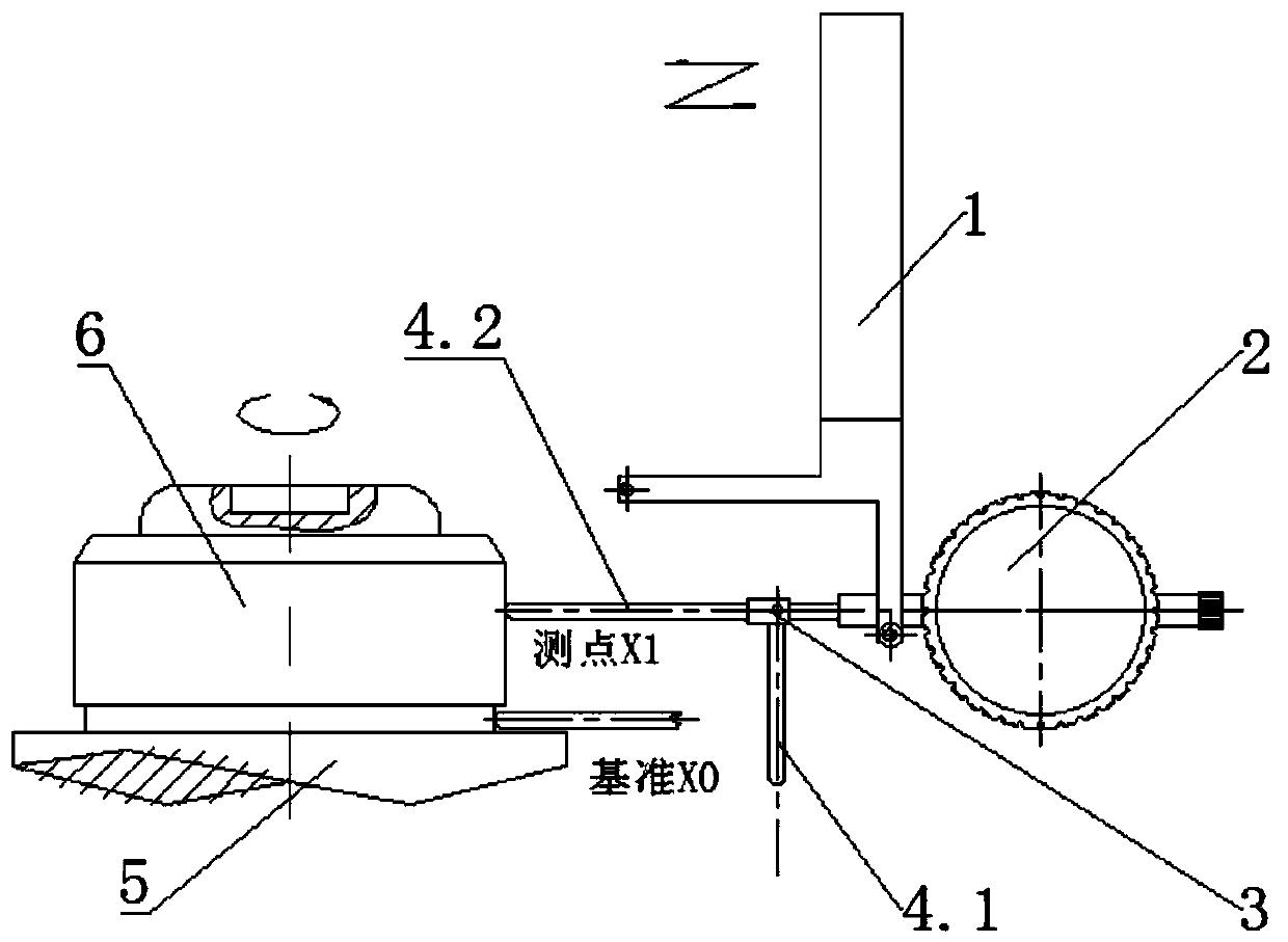
[0042] Such as Figure 1-3 As shown, based on the principle of error separation and the method of datum transformation, the adapter 3, the dial indicator 2 and the standard tool holder are integrated and designed, and the on-site precise measurement function of the rotating parts is realized by the machine tool numerical control system. An on-machine measuring device suitable for rotating parts with energy, including a suction cup 5 for absorbing a workpiece 6, and also includes a table frame 1, a measuring instrument, an adapter 3, and a stylus. The table frame 1 adopts a standard tool holder design, It can be freely installed and used on various CNC lathes, and a vertical part and a horizontal part for flexible clamping of the dial gauge 2 are provided at the execution end of the cutter bar. The execution end of the table frame 1 can flexibly hold the measuring instrument along the vertical and horizontal directions respectively, and the stylus includes a vertical stylus 4.1...

Embodiment 2

[0046] Such as figure 1 with Figure 4 As shown, the present invention also provides a method suitable for on-machine measurement of the outer diameter of an energetic rotating part, including the measuring device described in Embodiment 1, comprising the following steps:

[0047] Step 1: Fix the suction cup 5 on the end face of the machine tool spindle, and use the "self-turning" method to complete the machining of the X0 column section of the outer diameter process reference (generally the cylindricity is less than 0.003mm), and measure the XO value;

[0048] Step 2: complete the machining of the outer cylinder X1 of the workpiece 6 by cutting;

[0049] Step 3: Invoke the whole set of measuring devices on the table frame 1, start the outer diameter measurement program, rotate the spindle at low speed, first measure the outer diameter reference X0 of the suction cup 5 with the horizontal stylus 4.2 (coordinate value, return the dial gauge 2 to zero), and follow the numerical...

Embodiment 3

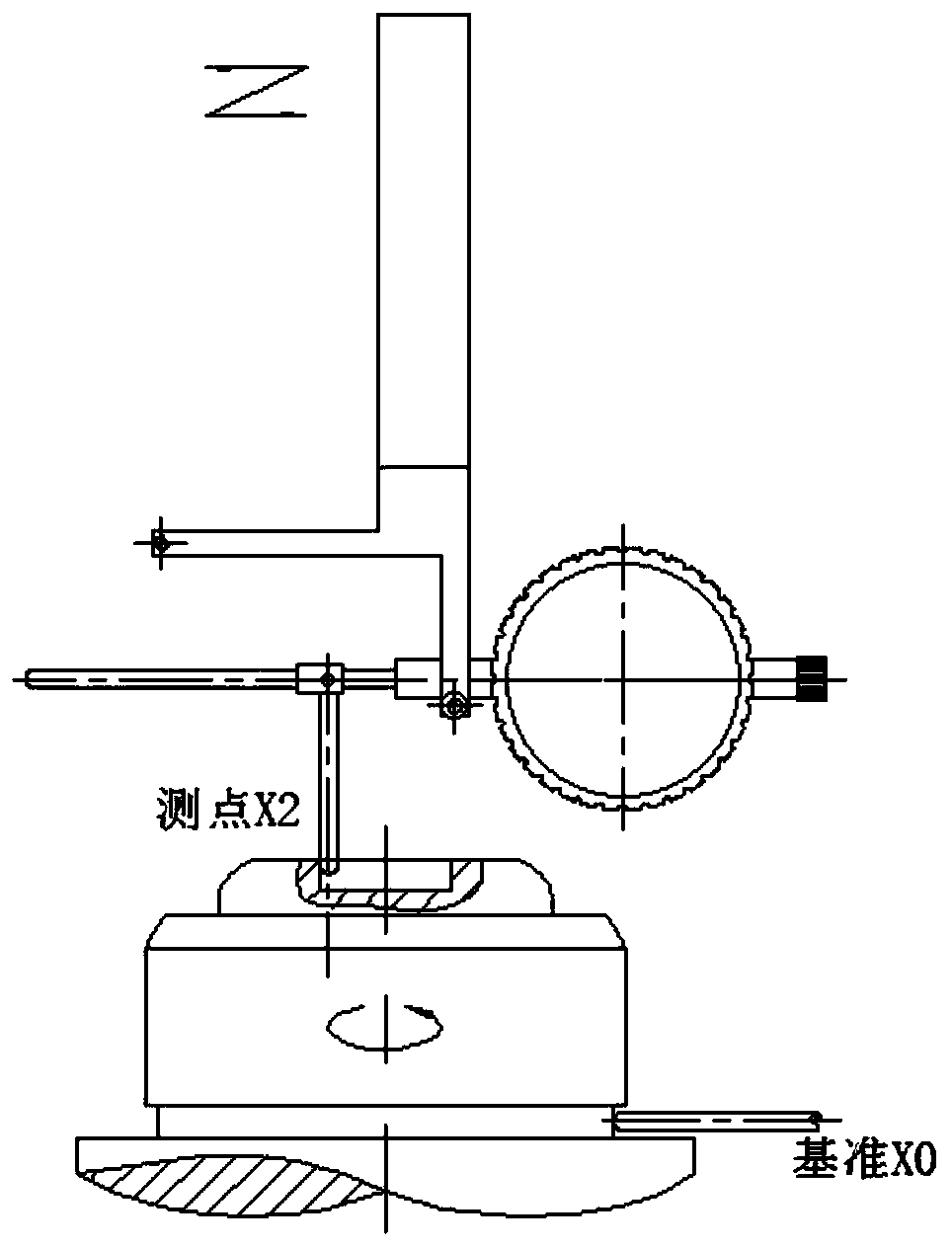
[0052] Such as figure 2 with Figure 4 As shown, the present invention also provides a method suitable for on-machine measurement of the inner diameter of a blind hole suitable for an energetic rotating part, including the measuring device described in Embodiment 1, comprising the following steps:

[0053] Step 1: Fix the suction cup 5 on the end face of the machine tool spindle, and use the "self-turning" method to complete the machining of the X0 column section of the outer diameter process reference, and measure the XO value (this operation is not required if it already exists);

[0054] Step 2: Complete the machining of workpiece 6 blind hole X2 by cutting;

[0055] Step 3: Invoke the entire set of measuring devices on the table frame 1, start the blind hole inner diameter measurement program, rotate the main shaft at a low speed, first use the vertical probe 4.1 to measure the outer diameter reference X0 of the suction cup 5 (coordinate value, return the dial gauge 2 to...


PUM


Abstract

The present invention discloses an on-machine measuring device and measuring method applicable to energetic rotating parts, and belongs to the technical field of composite material machining. The measuring device comprises a suction cup for adsorbing a workpiece, a table holder, a measuring instrument, an adapter, and a stylus; the table holder is arranged on a numerically controlled machine tool;the execution end of the table holder can flexibly clamp the measuring instrument in vertical and horizontal directions; the stylus comprises a vertical stylus and a horizontal stylus; the measuringinstrument can be provided with the vertical stylus and the horizontal stylus through the adapter; and the vertical stylus and the horizontal stylus are both in centering contact with the workpiece and are in the same plane. The method of reference transformation and error separation can be used to measure the three characteristic dimensions of the outer diameter, the inner hole and the height; and multi-point synchronous measurement can be used in the measuring device to realize the in-situ measurement function independent of the feed accuracy of the machine tool. According to the measuring device and measuring method provided by the present invention, based on the mature mechanical cutting technology of energetic materials, the shortcomings of the prior art are overcome, and an automaticand accurate in-situ measuring method with functional integration and convenient operations is provided.

Description

technical field [0001] The invention relates to the technical field of machining of composite materials, and more specifically relates to a device and a measurement method suitable for on-machine measurement of energetic rotating parts. Background technique [0002] High-energy explosives PBX (Polymer Bonded Explosives, polymer bonded explosives) is a kind of energy-containing functional material with excellent comprehensive performance, which is widely used in various weapon systems of land, sea, air and the Second Artillery. With the rapid development of weapons and equipment systems, the demand for precision machining of various energetic material components is also increasing day by day, and it is very urgent to improve the automation level of the machining process. Especially for the turning processing of rotating body parts with a rapidly increasing number, the in-situ inspection process of its common dimensional features (outer diameter, inner diameter, and height) ca...

Claims


Application Information

Patent Timeline
Patent Type & Authority Applications(China)
IPC IPC(8): G01B5/08G01B5/12G01B5/02G01B5/004G05B19/401
CPCG01B5/004G01B5/02G01B5/08G01B5/12G05B19/401G05B2219/37457
Inventor 曹志民刘婷黄交虎刘维唐世龙吴松
Owner INST OF CHEM MATERIAL CHINA ACADEMY OF ENG PHYSICS
Why Eureka
Try Eureka