Eureka AIR delivers breakthrough ideas for toughest innovation challenges, trusted by R&D personnel around the world.

Detection system for overload control at source and detection method thereof

A detection system and detection method technology, applied in transmission systems, instruments, electrical components, etc., can solve the problems of high network deployment difficulty, high network dependence, high cost, etc., and achieve outstanding network integration, low network dependence, and high cost. The effect of improving the efficiency of use

Inactive Publication Date: 2020-01-03
合肥市正茂科技有限公司
View PDF11 Cites 4 Cited by
  • Summary
  • Abstract
  • Description
  • Claims
  • Application Information

AI Technical Summary

Problems solved by technology

[0002] Source control of excess generally refers to the vehicle overload detection system set up at the source of freight such as mines, ports, and construction sites. It is transmitted to the upper-level platform through the network, and the traffic management department conducts supervision through the platform. This kind of system makes the coupling degree between each equipment site higher, and has the following disadvantages at the same time;
[0003] 1: The data transmission of the system is highly dependent on the network. Because some freight source units are located in remote mines and other places, the network deployment is difficult, and the transmission is unstable when using wireless network communication. In actual operation, the relevant data can only be transmitted to the upper platform Carry out supervision and processing, and the overrun of freight vehicles is a subjective activity, and it is not ruled out that relevant personnel disrupt network communications or intentionally power off network equipment;
[0004] 2: There are many information collection equipment and the cost is relatively high; because some freight sources are temporarily set up, such as construction and other places, due to limited physical conditions, it is not suitable to install more equipment;
[0005] 3: The traditional source super-governance system relies too much on the integrated use of the network, and the network dependence between each subsystem is high. Once a subsystem network failure occurs, it will directly affect the governance efficiency

Method used


Image

  • Detection system for overload control at source and detection method thereof

Examples


Embodiment Construction

[0023] The present invention will be further described below in conjunction with accompanying drawing:

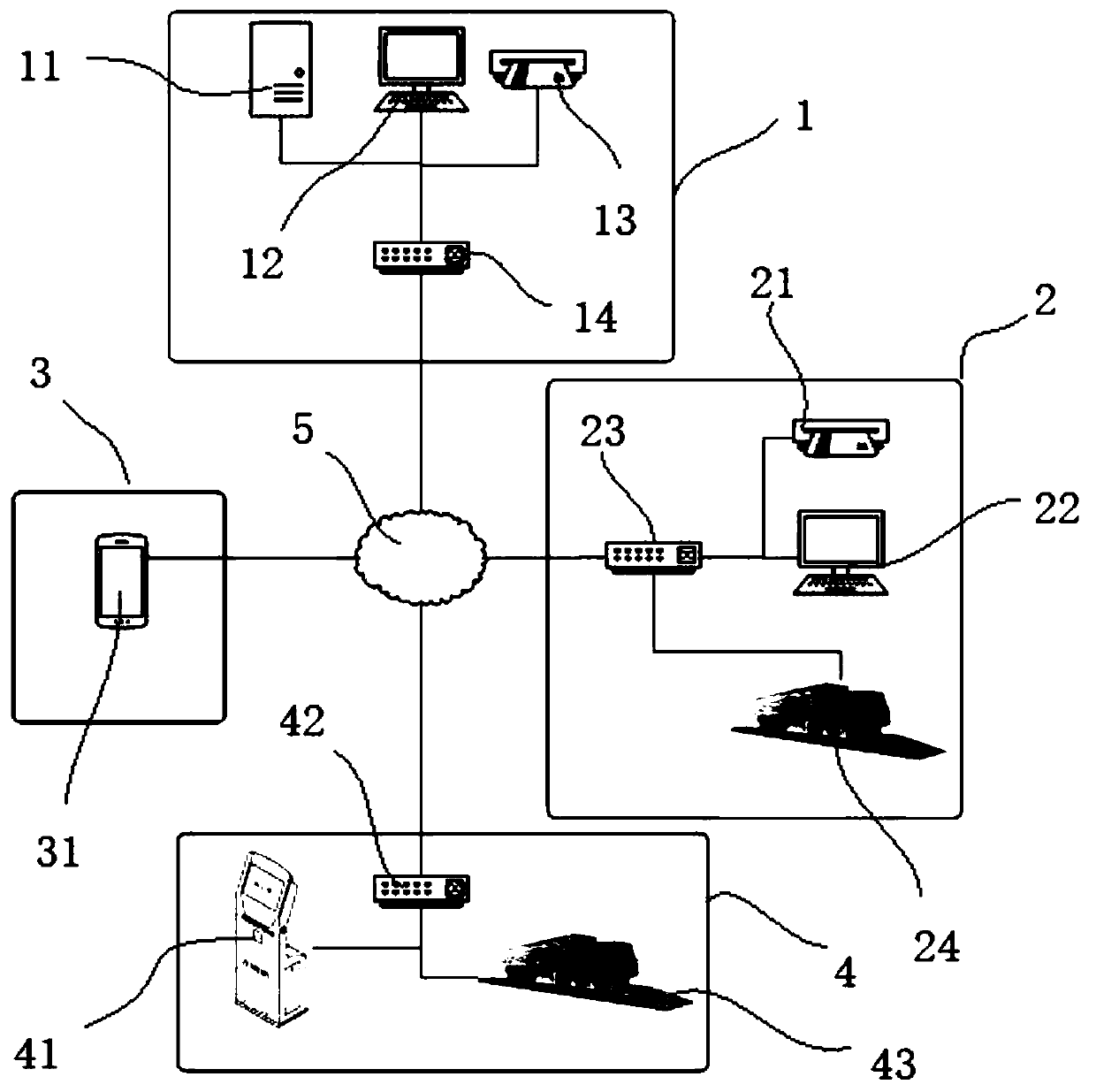
[0024] Such as figure 1 A detection system for source control, the detection system includes a management system 1, a source collection system 4, a fixed-point detection system 2 and a mobile inspection system 3;

[0025] The management system 1 includes a read-write device 12 for loading initial vehicle information, a writing device 13 for loading initial vehicle information, a server terminal 11 for platform manipulation, and a switch 14 for network connection , what needs to be explained is as follows;

[0026] First of all, the reading and writing equipment 12 adopted in the management system 1 generally adopts a traditionally used computer, and the computer is connected to a server terminal 11, and the server terminal 11 is used to collect and summarize the information data of each subsystem and process it , the specific data processed will be introduced one by one i...


PUM


Abstract

The invention discloses a detection system for overload control at source and a detection method thereof, and the detection system comprises a management system, a source collection system, a fixed point detection system and a mobile inspection system, wherein the source collection system and the fixed point detection system both comprise detection equipment used for detecting current informationof vehicles and entry equipment used for entering the current detection information into the write-in equipment, and the mobile inspection system comprises mobile equipment used for reading the write-in equipment. The invention, by using the management system to manage the initial information of vehicles and carrying the initial information on the drivers through the write-in equipment, has the outstanding function of separating the vehicle information and the management system from the network cloud, realizing independent detection processing of each subsystem to the vehicles under the condition that the management system does not establish network interconnection with each subsystem, enabling the support of delayed submission of detection information, and being suitable for various business requirements and installation environments.

Description

technical field [0001] The invention relates to the technical field of vehicle control, in particular to a detection system and a detection method for controlling overruns at the source. Background technique [0002] Source control of excess generally refers to the vehicle overload detection system set up at the source of freight such as mines, ports, and construction sites. It is transmitted to the upper-level platform through the network, and the traffic management department conducts supervision through the platform. This kind of system makes the coupling degree between each equipment site higher, and has the following disadvantages at the same time; [0003] 1: The data transmission of the system is highly dependent on the network. Because some freight source units are located in remote mines and other places, the network deployment is difficult, and the transmission is unstable when using wireless network communication. In actual operation, the relevant data can only be...

Claims


Application Information

Patent Timeline
IPC IPC(8): G07C9/00H04L29/08
CPCH04L67/12
Inventor 夏立志吕强王晨杨
Owner 合肥市正茂科技有限公司
Why Eureka
Eureka Blog
Learn More