
Pitching synchronous driving mechanism of dual-frequency communication-in-motion antenna

A technology of synchronous drive and frequency movement, which is applied in the field of satellite communication equipment, can solve the problems of transmission chain length, overall system stability, transmission accuracy, installation area occupied by the height of the whole machine, weight of the whole machine, and unfavorable cost, etc., so as to reduce the center of mass Effects of height, reduction of eccentric moment of inertia, and weight reduction

Pending Publication Date: 2020-01-03
航天恒星空间技术应用有限公司
View PDF0 Cites 0 Cited by
  • Summary
  • Abstract
  • Description
  • Claims
  • Application Information

AI Technical Summary

Problems solved by technology

For the dual-band Ku / Ka panel antenna, in general, the Ku antenna and the Ka antenna do not need to work at the same time. The general scheme is that the two antennas are arranged in the same direction, but in order to avoid beam occlusion and pitch rotation interference, the pitch axes of the two antennas It must be separated by a certain distance, and generally there will be a certain height difference; for the drive system, two sets of drives are generally used to work independently or a single set of linkage, but the drive chain of the single drive form must be made very long. The overall stability of the system, the transmission accuracy, the height of the whole machine, the installation area occupied by the whole machine, the weight of the whole machine, and the cost have brought many disadvantages.

Method used


Image

  • Pitching synchronous driving mechanism of dual-frequency communication-in-motion antenna
  • Pitching synchronous driving mechanism of dual-frequency communication-in-motion antenna
  • Pitching synchronous driving mechanism of dual-frequency communication-in-motion antenna

Examples


Embodiment Construction

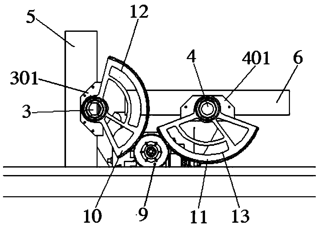
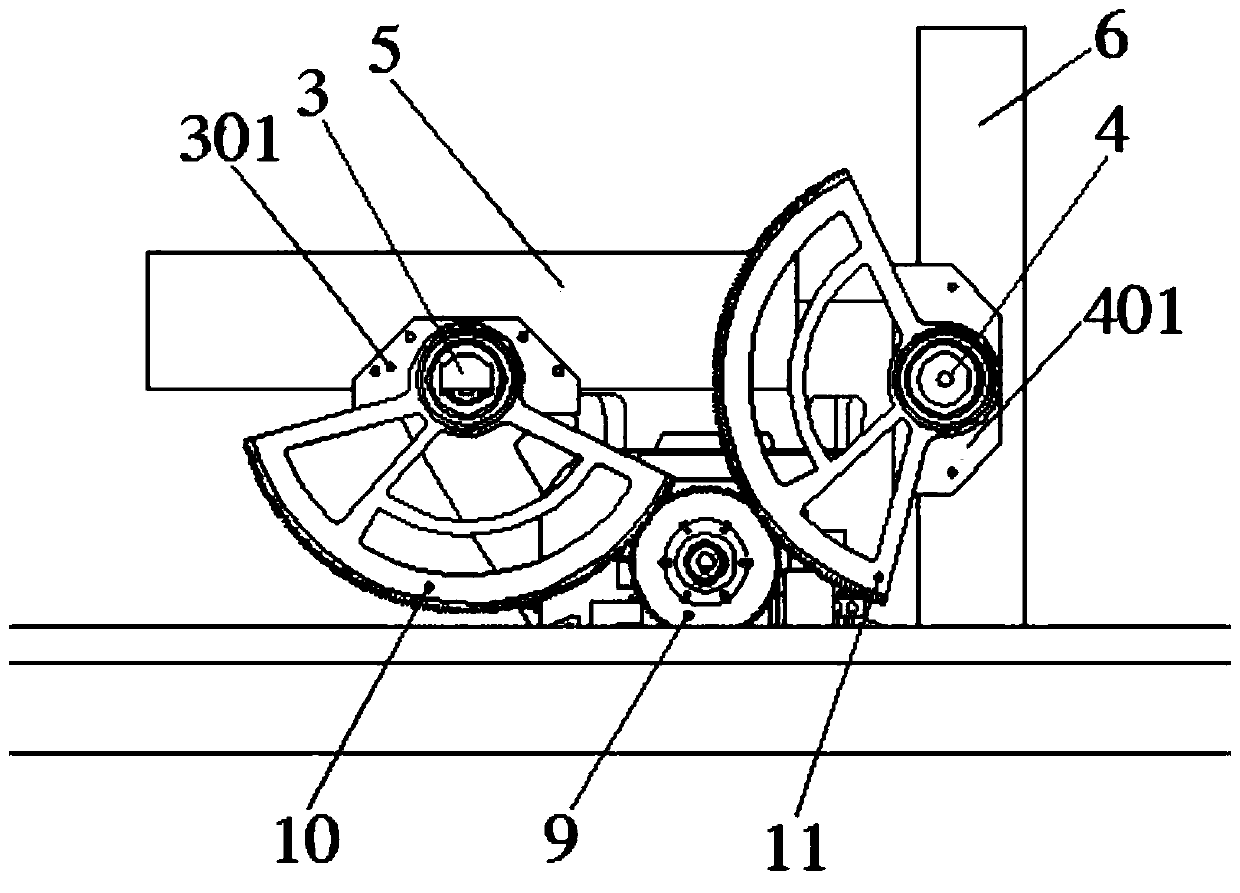
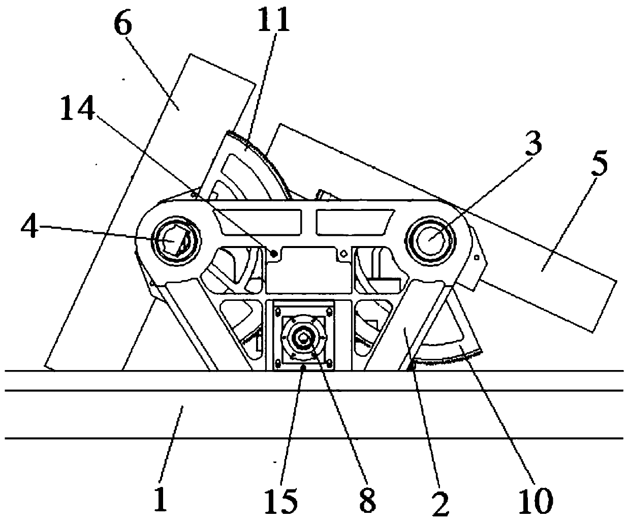
[0023] refer to figure 1 and figure 2 , the present invention is an embodiment of a dual-frequency mobile antenna pitch synchronous drive mechanism, including: an azimuth rotary platform 1 and a motor and encoder combination 8, the azimuth rotary platform 1 is provided with a support arm 2, and the support arm 2 rotates A first axis 3 and a second axis 4 are provided, the first axis 3 is parallel to the second axis 4, a Ku panel antenna 5 is rotatably arranged on the first axis 3, and a Ka panel antenna 6 is rotatably arranged on the second axis 4, The Ku panel antenna 5 is perpendicular to the face of the Ka panel antenna 6; the motor and encoder combination 8 is directly or indirectly assembled on the support arm 2, and the main shaft of the motor and encoder combination 8 is driven simultaneously with the Ku panel antenna 5 and the Ka panel antenna 6 connected, and the transmission ratio is equal, when the motor and encoder combination 8 drives the Ku panel antenna 5 to r...


PUM


Abstract

The invention discloses a pitching synchronous driving mechanism of a dual-frequency communication-in-motion antenna. The mechanism comprises an azimuth rotation platform and a motor. A support arm isarranged on the azimuth rotation platform. A first shaft and a second shaft are rotationally arranged on the support arm, and the first shaft is parallel to the second shaft. A Ku planar antenna is rotationally arranged on the first shaft, a Ka planar antenna is rotationally arranged on the second shaft, and the opening surface of the Ku planar antenna is perpendicular to the opening surface of the Ka planar antenna. A motor and encoder combination is directly or indirectly assembled on the support arm. A main shaft of the motor is in transmission connection with the Ku planar antenna and theKa planar antenna simultaneously, and the transmission ratios are equal. According to the pitching synchronous driving mechanism of the dual-frequency communication-in-motion antenna, the adjusting time is shortened, the adjusting precision is improved, the adjusting mechanism is simplified, the size of the mechanism is reduced, and the weight of the mechanism is reduced.

Description

technical field [0001] The invention belongs to the field of satellite communication equipment, and in particular relates to a pitch synchronous drive mechanism for a dual-frequency mobile mid-communication antenna. Background technique [0002] With the rapid development of modern satellite communication technology, the application of dual-frequency satellite communication antennas is becoming more and more extensive. In order to ensure that the antenna can track the target satellite, a stable satellite link is established. It is necessary to ensure that the transmission system of the servo tracking structure is stable and reliable. In order to ensure good tracking accuracy, it is necessary to reduce the hysteresis on the transmission chain as much as possible; for the gear transmission chain, the tooth backlash must be regulated. For the dual-band Ku / Ka panel antenna, in general, the Ku antenna and the Ka antenna do not need to work at the same time. The general scheme i...

Claims


Application Information

Patent Timeline
IPC IPC(8): H01Q3/04H01Q21/30H01Q1/32F16H1/22
CPCF16H1/22H01Q1/3275H01Q3/04H01Q21/30
Inventor 张少儒程鹏井蓬涛
Owner 航天恒星空间技术应用有限公司
Learn More