
General-purpose mechanical camshaft gear manufacturing device

A technology for camshaft gears and general machinery, which is applied in the direction of valve devices, mechanical equipment, manufacturing tools, etc., can solve the problems of high labor intensity and low work efficiency, and achieve the effect of strengthening the grinding effect

Active Publication Date: 2021-03-16
重庆九方铸造有限责任公司
View PDF6 Cites 0 Cited by
  • Summary
  • Abstract
  • Description
  • Claims
  • Application Information

AI Technical Summary

Problems solved by technology

At present, the grinding of the tooth grooves of helical gears is done manually with sandpaper, which has low work efficiency and high labor intensity.

Method used


Image

  • General-purpose mechanical camshaft gear manufacturing device
  • General-purpose mechanical camshaft gear manufacturing device
  • General-purpose mechanical camshaft gear manufacturing device

Examples


Embodiment 1

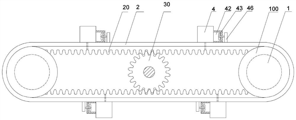
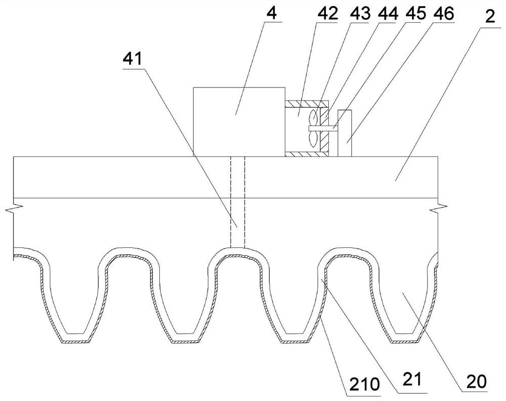
[0029] like figure 1 and figure 2 As shown, the general-purpose mechanical camshaft gear manufacturing device of this embodiment includes a moving mechanism for driving the camshaft gear 30 to move and a tooth groove grinding mechanism for grinding the tooth grooves of the camshaft gear 30 .

[0030] The cogging grinding mechanism includes two rotating rollers 1 and a belt 2 wound on the two rotating rollers 1. The rotating roller 1 is connected with a servo motor (not shown in the figure) to drive the rotating roller 1 to rotate, thereby driving the belt 2 Movement on two rotating rollers 1. The inner side of the belt 2 is provided with grinding teeth 20 which can mesh with the tooth grooves of the camshaft gear 30. The grinding teeth 20 are bonded with an air bag 21 wrapping the grinding teeth 20. The outer surface of the air bag 21 is provided with a grinding layer 210. The grinding layer 210 is Similar to the structure of sandpaper, the outer edge of the rotating roller...

Embodiment 2

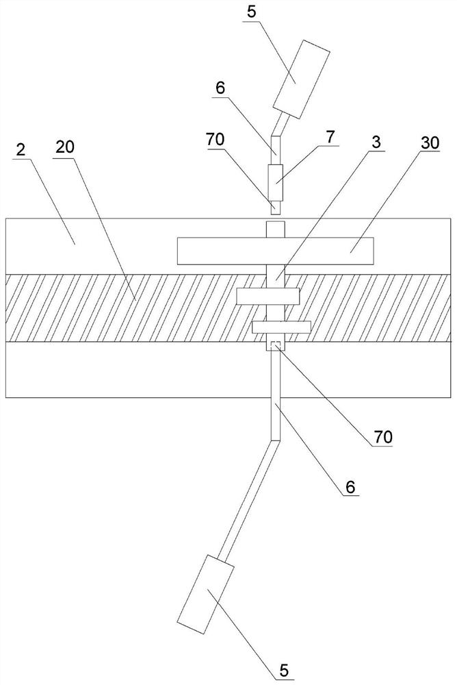
[0044] The difference between this embodiment and Embodiment 1 is that: Image 6 and Figure 7 As shown, this embodiment is used for grinding two camshaft gears 30 (of course, more than two camshaft gears 30 can also be polished according to actual needs), and each camshaft 3 is connected with a support rod 6 for support and positioning Each support rod 6 is connected with a connecting rod 8, and then the connecting rod 8 is fixed by the output rod of the linear motor 5 to drive each camshaft gear 30 to move.


PUM


Abstract

The invention belongs to the field of machine manufacturing and particularly discloses a device for manufacturing a gear for a universal machinery cam shaft. The device comprises a moving mechanism for driving a cam shaft gear to move and a tooth slot polishing mechanism for polishing the tooth slot of a cam shaft gear; the tooth slot polishing mechanism comprises two rotating rollers and a belt wound on the two rotating rollers; polishing teeth meshed with the teeth slot of the cam shaft gear are arranged on the inner side of the belt; an air sac wrapping the polishing teeth is arranged outside the polishing teeth; a polishing layer is arranged on the outer surface of the air sac; the air sac is connected with an air inflating and releasing mechanism; the moving mechanism comprises two support pieces and a motion driving piece; the two support pieces are used for clamping and supporting the cam shaft from the two ends of the cam shaft; and the motion driving piece is used for drivingthe support pieces to move in the length direction of the polishing teeth on the belt.

Description

technical field [0001] The invention relates to the field of mechanical manufacturing, in particular to a gear manufacturing device for general mechanical camshafts. Background technique [0002] Camshaft gears are mainly processed and formed by shaving. After shaving the camshaft gears, there are burrs in the tooth grooves of the gears, and the gear tooth grooves need to be polished. The existing gear grinding devices are usually for spur gears. Grinding, not suitable for tooth groove grinding of helical gears. At present, the tooth grooves of helical gears are polished manually with sandpaper, which has low work efficiency and high labor intensity. Contents of the invention [0003] The purpose of the present invention is to provide a gear manufacturing device for a general mechanical camshaft, capable of grinding the tooth grooves of the helical gear on the camshaft. [0004] To achieve the above object, the present invention adopts the following technical solutions: ...

Claims


Application Information

Patent Timeline
Patent Type & Authority Patents(China)
IPC IPC(8): B24B15/08F01L1/047
CPCB24B15/08F01L1/047
Inventor 胡艾滔
Owner 重庆九方铸造有限责任公司
Learn More