Luggage tray horizontal distributing device

A technology of diverting device and tray, applied in the directions of transportation and packaging, conveyor, roller table, etc., can solve the problems of inability to control the synchronous deflection of deflection wheels and high equipment cost, and achieve flexible and ingenious structural design and low equipment use cost. , to ensure the effect of transmission reliability

Pending Publication Date: 2020-01-07
CIVIL AVIATION LOGISTICS TECH
View PDF1 Cites 0 Cited by
  • Summary
  • Abstract
  • Description
  • Claims
  • Application Information

AI Technical Summary

Problems solved by technology

[0007] The purpose of the present invention is: in order to solve the technical problem that three or more servo motors need to be used to drive the deflection of the deflection wheels in the existing logistics sorting device, the equipment cost is high, and the synchronous deflection of all the deflection wheels cannot be well controlled. The invention provides a luggage pallet horizontal diversion device

Method used


Image

  • Luggage tray horizontal distributing device
  • Luggage tray horizontal distributing device
  • Luggage tray horizontal distributing device

Examples


Embodiment 1

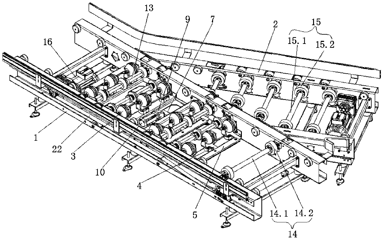
[0041] Such as Figures 1 to 10 As shown, this embodiment provides a luggage pallet horizontal distribution device, including a main line rack 1, a branch line rack 2 is connected to the side end of the main line rack 1, and a distribution unit is arranged on the main line rack 1 near the branch line rack 2 , the splitter unit includes several deflection mechanisms 3 arranged vertically and horizontally. The deflection mechanisms 3 are rotatably connected to the main line frame 1. The side ends of the deflection mechanisms 3 are connected with crank connecting rods A4 parallel to the length direction of the main line frame 1. The same horizontal The deflection mechanisms 3 in the row are all connected with the transverse link 5 through the crank connecting rod A4, the transverse link 5 is perpendicular to the length direction of the main line frame 1, and the bottom of the deflection mechanism 3 in the middle row is connected with a The crank connecting rod B6 and the crank co...

Embodiment 2

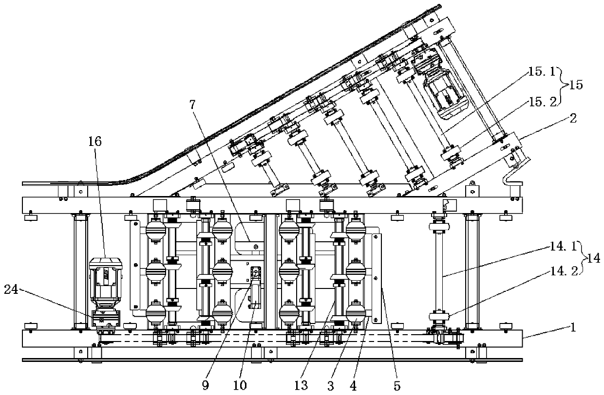
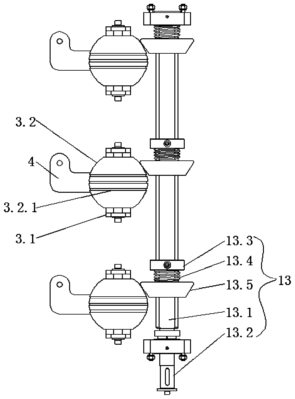
[0044] Such as Figures 1 to 7 As shown, this embodiment is further optimized on the basis of Embodiment 1. Specifically, the deflection mechanism 3 includes a support frame 3.1, a deflection ball 3.2 is movably connected to the support frame 3.1, and the deflection ball 3.2 is connected to the bottom of the support frame 3.1. There is a gap between them, the bottom end of the support frame 3.1 is connected with the crank connecting rod A4, the bottom of the support frame 3.1 is connected with the rotating shaft 3.3, the rotating shaft 3.3 is movably connected on the main line frame 1, the bottom of the rotating shaft 3.3 is connected with the crank connecting rod B6, and the main line The frame 1 is rotatably provided with several drive mechanisms 13, the drive mechanism 13 is perpendicular to the length direction of the main line frame 1, and the drive mechanism 13 can drive the deflection balls 3.2 in the same horizontal row to rotate simultaneously, and the deflection angle...

Embodiment 3

[0049] Such as Figures 1 to 11 As shown, this embodiment is further optimized on the basis of Embodiment 2. Specifically, the main line frame 1 is provided with a DC unit A14 located in front of the distribution unit along its conveying direction, and the branch line frame 2 is provided with DC unit B15, DC unit A14 includes a number of rollers A14.1 movably connected to the main line frame 1, at least two rollers A14.2 are fixedly sleeved on the roller A14.1, and DC unit B15 includes several rollers A14. The roller B15.1 on the branch line frame 2 has at least two rollers B15.2 fixedly sleeved on the roller B15.1.

[0050] The main line frame 1 is provided with a power unit that can drive the DC unit A14 and all driving mechanisms 13 to rotate. The power unit includes a driving motor B16 arranged on the main line frame 1. The driving motor B16 is connected to a reducer B24, and the reducer B24 is connected to There are driving wheels 17, and the side end of the main line fr...


PUM


Abstract

The invention discloses a luggage tray horizontal distributing device and relates to the technical field of logistics conveying. The luggage tray horizontal distributing device comprises a main line rack. A branch line rack is connected to the side end of the main line rack. A distributing unit is arranged on the area, close to the branch line rack, of the main line rack. The distributing unit comprises a plurality of deflection mechanisms arranged longitudinally and transversely. The deflection mechanisms are connected to the main line rack in a rotating manner. A crank connecting rod A is connected to each deflection mechanism. The deflection mechanisms on the same transverse row are connected with a transverse connecting rod through the crank connecting rods A. A crank connecting rod Blocated below the main line rack is connected to the bottom of each deflection mechanism on one middle longitudinal row. The same one longitudinal connecting rod is hinged to all the crank connectingrods B. A crank connecting rod C is hinged to the middle portion of the longitudinal connecting rod. A speed reducer located on the main line rack is connected to the crank connecting rod C. A drive motor A is connected to the speed reducer. The luggage tray horizontal distributing device has the advantages that only one drive motor is adopted for driving all the deflection mechanisms to rotate, and the equipment cost is reduced.

Description

technical field [0001] The invention relates to the technical field of logistics transportation, and more specifically relates to a luggage pallet horizontal distribution device. Background technique [0002] The automatic sorting system is an important branch of the material handling system, which is widely used in production logistics systems, logistics distribution centers or airport luggage delivery centers in various industries. The automatic sorting machine is mainly composed of feeding device, conveying device, control system, sorting device and sorting crossing. It is one of the key equipment for automatically sorting and sorting items. Divided according to the structure of the sorting device, the common automatic sorting machines mainly include slider sorting machine, rotary (or inclined wheel) sorting, cross-belt sorting, flap sorting machine, swing arm sorting sorter, floating sorter, tray sorter, hanging sorter and other types. [0003] In the airport baggage s...

Claims


Application Information

Patent Timeline
Patent Type & Authority Applications(China)
IPC IPC(8): B65G47/24B65G47/52B65G13/06B65G13/11
CPCB65G13/06B65G13/11B65G47/24B65G47/52B65G2201/0258B65G2201/0264
Inventor 毛刚李貌杨秀清王小锐何威杨文武李冰楠曹津源吴仕杰赵东飞
Owner CIVIL AVIATION LOGISTICS TECH
Why Eureka
Try Eureka