Direct current steam generator

A steam generator and burner technology, applied in steam generation, steam boilers, lighting and heating equipment, etc., can solve the problems of high operating cost, long start-up time, low reliability, etc., to avoid steam explosion, improve thermal efficiency, The effect of improving safety

Pending Publication Date: 2020-01-07
中国船舶重工集团公司第七0三研究所
View PDF0 Cites 3 Cited by
  • Summary
  • Abstract
  • Description
  • Claims
  • Application Information

AI Technical Summary

Problems solved by technology

[0004] The present invention solves the problems that traditional drum boilers have long start-up time and poor thermal efficiency, resulting in high operating costs, and the traditional boilers have large water capacity, sometimes there is the possibility of steam explosion, and the problems of low reliability, A once-through steam generator

Method used


Image

  • Direct current steam generator
  • Direct current steam generator
  • Direct current steam generator

Examples


specific Embodiment approach 1

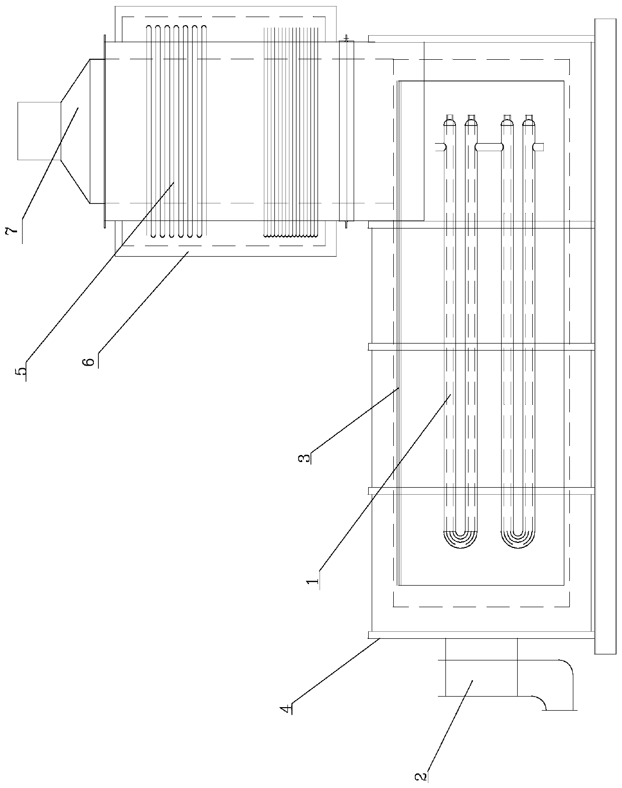
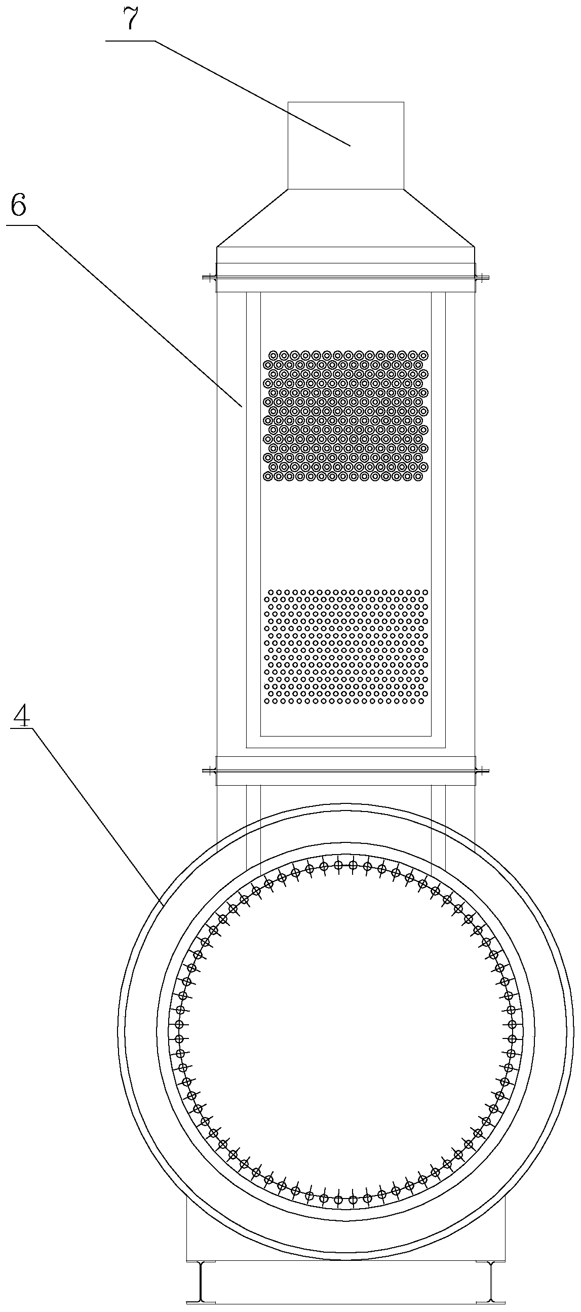
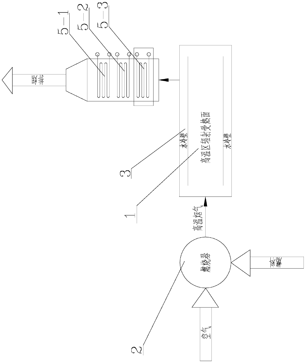
[0023] Specific implementation mode one: combine Figure 1 to Figure 4 To illustrate this embodiment, a once-through steam generator described in this embodiment includes a radiation heat receiving pipe 1 in a high temperature zone, a burner 2, a water wall 3, a lower part of the housing 4, a convective heating unit 5 in a low temperature zone, and an upper part 6 of the housing;

[0024] The lower part 4 of the housing is cylindrical, and one end of the lower part 4 of the housing is provided with a burner 2, and the burner is connected to the lower part 4 of the housing, and the lower part 4 of the housing is provided with n high-temperature zone radiation heat receiving pipes 1, n It is a positive integer and arranged in parallel. The inner wall of the lower part of the housing 4 is evenly provided with m water-cooled walls 3 along the circumferential direction, m is a positive integer, and the other end of the lower part of the housing 4 is provided with an upper part of th...

specific Embodiment approach 2

[0026] Specific implementation mode two: combination figure 2 Describe this embodiment. This embodiment is a further limitation on the generator described in Embodiment 1. In the direct-flow steam generator described in this embodiment, the top end of the lower part 4 of the housing is provided with a smoke exhaust Mouth 7.

specific Embodiment approach 3

[0027] Specific implementation mode three: combination figure 2 Describe this embodiment, this embodiment is a further limitation on the generator described in the second specific embodiment, a direct-flow steam generator described in this embodiment, the smoke exhaust port 7 is a tapered port;

[0028] In this specific embodiment, the smoke exhaust port 7 is adopted as a tapered port, so that the smoke can be discharged in one place.


PUM


Abstract

The invention discloses a direct current steam generator and relates to the field of steam generators. The direct current steam generator solves the problems that the operating cost is relatively highas a conventional drum boiler is relatively long in starting time and relatively poor in heat efficiency, and a conventional boiler which is relatively large in water volume has the probability of steam explosion and is relatively low in reliability. The lower part of a shell is cylindrical, a burner is arranged at one end of the lower part of the shell, the burner communicates to the lower partof the shell, n high-temperature area radiating heated pipes are arranged in the lower part of the shell, n is a positive integer and the high-temperature area radiating heated pipes are parallelly arranged, m water cooling walls are uniformly arranged on the inner wall of the lower part of the shell along the circumferential direction, m is a positive integer, an upper part of the shell is arranged on the outer surface of the other end of the lower part of the shell circumferentially, the upper part of the shell communicates to the lower part of the shell, and a low-temperature area convection heated unit is vertically arranged in the upper part of the shell. The direct current steam generator is suitable for the fields of chemical engineering, casting, movable heating, pharmacy and disinfection and can be also applied to a steam-injection mining steam-injection boiler of an oil field and a starting furnace of a power station.

Description

technical field [0001] The invention relates to the field of steam generators, in particular to a direct-flow steam generator. Background technique [0002] For more than one hundred years, boilers have been widely used in various industrial fields as traditional general-purpose equipment. The start-up loss of traditional drum boilers generally ranges from 2 to 20% of the daily fuel cost, and depends on the number of starts, the size of the boiler and the steam system, after a long period of operation, this loss will accumulate hugely. At the same time, the natural circulation type drum boiler consumes a lot of metal and has a lagging response to regulation. These shortcomings have seriously restricted its development and application in the future. [0003] To sum up, the traditional drum boiler takes a long time to start and has poor thermal efficiency, which leads to high operating costs. Moreover, the traditional boiler has a large water capacity, sometimes there is a po...

Claims


Application Information

Patent Timeline
IPC IPC(8): F22B31/00F22B31/08
CPCF22B31/00F22B31/08
Inventor 尤建华王军
Owner 中国船舶重工集团公司第七0三研究所
Why Eureka
Try Eureka