
Complex environment foundation pit excavation hole-by-hole blasting method

A technology of complex environment and detonation method, which is applied in excavation, blasting, infrastructure engineering, etc., can solve the problems of slow forming cycle of foundation pit excavation, high cost of foundation pit excavation, vibration, etc., so as to improve the blasting effect and reserve The effect of small disturbance of rock mass and high average vibration reduction rate

Inactive Publication Date: 2020-01-07
KUNMING UNIV OF SCI & TECH +1
View PDF5 Cites 8 Cited by
  • Summary
  • Abstract
  • Description
  • Claims
  • Application Information

AI Technical Summary

Problems solved by technology

[0004] The present invention aims at blasting operations in a complex environment where there are residential areas, large-scale breeding farms, or important building facilities within 100m of the edge of the blasting area. Problems such as slow digging cycle and high cost of foundation pit excavation; a method of detonation hole by hole in complex environment is proposed, which can well solve the vibration problem of foundation pit excavation on surrounding buildings under complex environment conditions

Method used


Image

  • Complex environment foundation pit excavation hole-by-hole blasting method
  • Complex environment foundation pit excavation hole-by-hole blasting method
  • Complex environment foundation pit excavation hole-by-hole blasting method

Examples


Embodiment 1

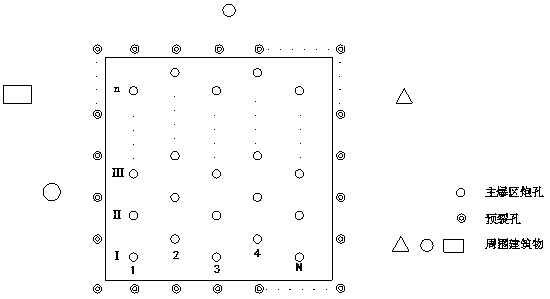
[0032] Embodiment 1: The complex environment schematic diagram of this embodiment is as follows Figure 8 As shown, the rock properties are medium-hard rocks, the rock-soil properties are stable, and the joints and fissures are not developed;

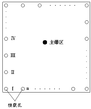
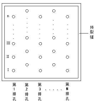
[0033] Such as Figure 1~8 As shown, a hole-by-hole detonation method for foundation pit excavation in complex environment, the specific steps are as follows:

[0034] (1) Pre-splitting holes are evenly arranged on the excavation contour line of the foundation pit in a complex design environment, and a radial non-coupling charge device is installed in the pre-splitting hole, and the non-coupling charge in the pre-splitting hole is controlled by a digital electronic detonator and detonated hole by hole;

[0035] (2) Clean up the pre-splitting blasting pile, arrange several rows of staggered main blasting holes in the main blasting area of ​​the excavation surface of the foundation pit, the row spacing of the main blasting holes is equal...

Embodiment 2

[0049] Embodiment 2: The complex environment is that there are residential areas and large-scale breeding farms within 100m of the edge of the blasting area; the rock properties are soft rocks with drillability, and joints and fissures are developed;

[0050] The hole-by-hole detonation method for foundation pit excavation in complex environment in this embodiment is basically the same as that in Embodiment 1, except that:

[0051] The hole spacing of the pre-splitting hole is 10 times the diameter of the pre-splitting hole, and the delay time of the digital electronic detonator of the pre-splitting hole is 16ms;

[0052] The delay time between the main blast hole holes and the delay time between the main blast hole rows in the main blast area is determined according to the ore rock properties in the main blast area. The row spacing of the gun holes is 0.85 times the hole spacing of the main gun holes, the delay time between the digital electronic detonators of the main gun hole...

Embodiment 3

[0054] Embodiment 3: The complex environment is that there are ancient buildings to be protected within 100m of the edge of the blasting area; the rock properties are hard and compact rocks with drillability, and the joints and fissures are not developed;

[0055] The hole-by-hole detonation method for foundation pit excavation in complex environment in this embodiment is basically the same as that in Embodiment 1, except that:

[0056] The hole spacing of the pre-splitting hole is 8 times the diameter of the pre-splitting hole, and the delay time of the digital electronic detonator of the pre-splitting hole is 22ms;

[0057] The delay time between the main blast hole holes and the delay time between the main blast hole rows in the main blast area is determined according to the ore rock properties in the main blast area. The row spacing of the gun holes is 0.9 times the hole spacing of the main gun holes, the delay time between the digital electronic detonators of the main gun...


PUM


Abstract

The invention relates to a complex environment foundation pit excavation hole-by-hole blasting method and belongs to the technical field of blasting. The complex environment foundation pit excavationhole-by-hole blasting method comprises the steps of uniformly arranging presplitting holes in a designed complex environment foundation pit excavation contour line, arranging uncoupling explosive charging devices in the presplitting holes, and controlling the uncoupling explosive charging devices in the presplitting holes to conduct accurate delay hole-by-hole blasting through digital electronic detonators; and cleaning presplitting blasting muck piles, and arranging a plurality of staggered main blasting holes in a main blasting region of a foundation pit excavation face, wherein the row pitches of the main blasting holes are equal, and the hole distances of the main blasting holes are equal. The uncoupling explosive charging devices are arranged in the presplitting holes. The uncouplingexplosive charging devices in the main blasting holes control accurate delay row-by-row hole-by-hole blasting through the digital electronic detonators, and then the blasting muck piles in the main blasting region are cleaned. Through the complex environment foundation pit excavation hole-by-hole blasting method, the foundation pit forming time is quick. Compared with the presplitting hole simultaneous blasting method, the presplitting hole hole-by-hole blasting method has the advantages that the average vibration reduction rate is high, vibration generated during main blasting region hole-by-hole blasting is greatly reduced, meanwhile, the presplitting holes are detonated to form a new free face first, and the blasting effect is greatly improved.

Description

technical field [0001] The invention relates to a hole-by-hole detonation method for foundation pit excavation in a complex environment, belonging to the technical field of blasting. Background technique [0002] During the blasting operation, when the explosive explodes in the blasthole, a strong shock wave and high-pressure gas will be generated, causing the surrounding rock mass to break and crack. In many projects in our country, such as open-pit mine slopes, hydraulic constructions, traffic cuttings, building foundation pits, tunnels and excavation of underground buildings, etc., it is necessary to control the blasting boundary, reduce blasting vibration, and avoid over-excavation and under-excavation. At the same time, it is also necessary to keep the rock mass on the excavation boundary as complete and stable as possible. [0003] With the shortage of engineering land, the environment around excavation of foundation pits is becoming more and more complicated. In the...

Claims


Application Information

Patent Timeline
Patent Type & Authority Applications(China)
IPC IPC(8): F42D1/00F42D3/04E02D17/02
CPCF42D1/00F42D3/04E02D17/02
Inventor 李祥龙袁芝斌张其虎侯猛王子琛母永烨张希陈浩李在利唐锐段应明
Owner KUNMING UNIV OF SCI & TECH
Learn More