Sulfur hexafluoride arc-extinguishing chamber structure

A technology of sulfur hexafluoride and arc extinguishing chamber, which is applied in the direction of high-voltage air circuit breakers, electrical components, electric switches, etc., can solve the problems of small contact displacement distance and secondary breakdown, so as to ensure electrical safety and open The effect of outstanding breaking ability and eliminating potential safety hazards

Pending Publication Date: 2020-01-07
宁波鑫鑫鑫寅电气有限公司
View PDF0 Cites 0 Cited by
  • Summary
  • Abstract
  • Description
  • Claims
  • Application Information

AI Technical Summary

Problems solved by technology

Most of the sulfur hexafluoride interrupters in the prior art are air-blown vacuum interrupters, that is, the movement of the movable contact is used to generate a pressure difference in the sulfur hexafluoride gas in the interrupter, and then the sulfur hexafluoride gas is Blow to the disconnected position of the moving and static contacts for arc extinguishing, but because the current on the moving contacts is not lowered in this way, it is only suitable for arc extinguishing environments with small current and low voltage, while for high current and high voltage If the arc extinguishing environment is too small, it will cause secondary breakdown due to the small displacement distance of the contact, posing a safety hazard

Method used


Image

  • Sulfur hexafluoride arc-extinguishing chamber structure
  • Sulfur hexafluoride arc-extinguishing chamber structure
  • Sulfur hexafluoride arc-extinguishing chamber structure

Examples


Embodiment Construction

[0033] The present invention will be described in further detail below in conjunction with the accompanying drawings.

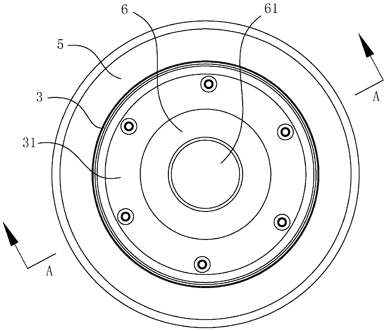
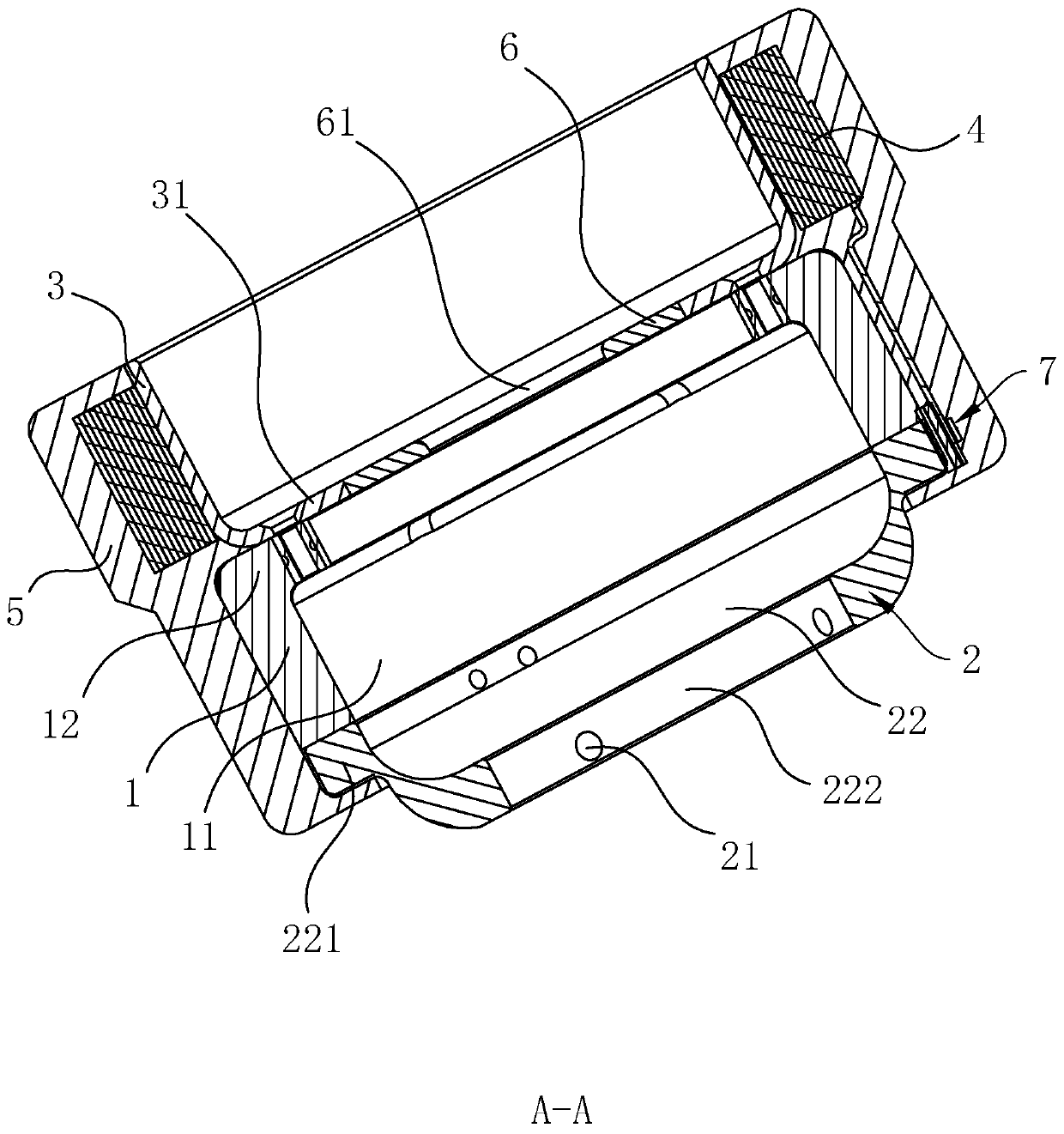
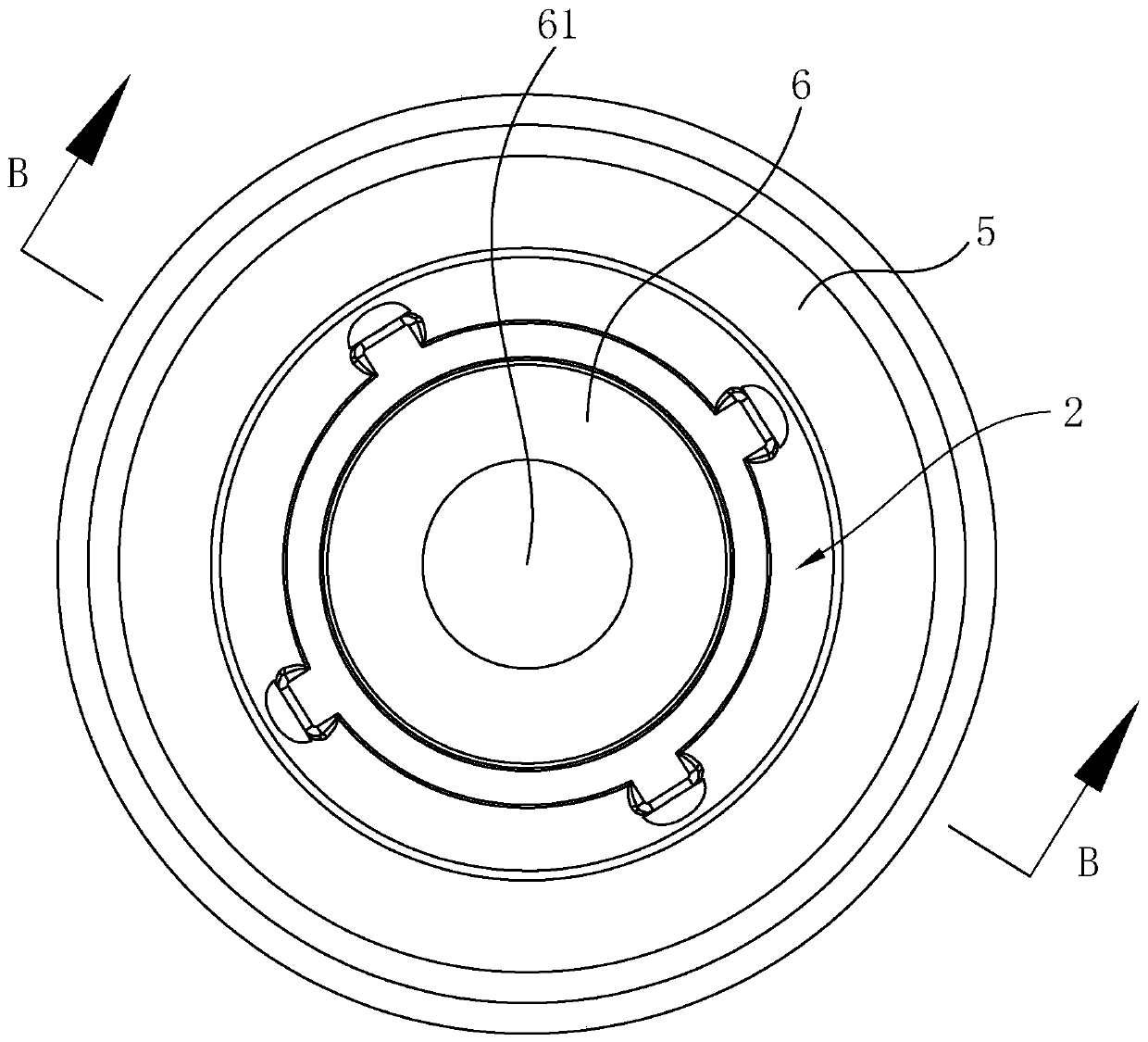
[0034] refer to figure 1 and figure 2 , a sulfur hexafluoride arc extinguishing chamber structure disclosed in the present invention, including an insulating support sleeve 1 with an arc extinguishing chamber 11 inside, an end cover 2 arranged at one end of the insulating support sleeve 1 for connecting a static contact, and an end cover 2 arranged on an insulating The other end of the support sleeve 1 is used to connect the conductive voltage-reducing and current-reducing component of the moving contact. The end cover 2 is provided with an air hole 21 for passing sulfur hexafluoride gas into the arc extinguishing chamber 11. The conductive voltage-reducing and current-reducing component includes The conductive sleeve 3 fixed on the end surface of the insulating support sleeve 1 and the conductive step-down and current-reducing belt 4 wound on the outer wal...


PUM


Abstract

The invention relates to a sulfur hexafluoride arc-extinguishing chamber structure, which comprises an insulation supporting sleeve having an arc-extinguishing chamber inside, an end cover arranged atone end of the insulation supporting sleeve and used for being connected with a static contact, and a conductive voltage-reduction and current-reduction assembly arranged at the other end of the insulation supporting sleeve and used for being connected with a moving contact. Air holes are formed in the end cover. The conductive voltage-reduction and current-reduction assembly comprises a conductive sleeve and a conductive voltage-reducing and current-reducing belt wound on the outer wall of the conductive sleeve. One end of the conductive voltage-reducing and current-reducing belt is fixed tothe outer wall of the conductive sleeve, and the other end of the conductive voltage-reducing and current-reducing belt is fixed to the outer wall of the end cover. The outer walls of the conductivesleeve, the insulation supporting sleeve and the end cover are respectively provided with an insulated protective layer; and the conductive voltage-reducing and current-reducing belt is wrapped in theinsulated protective layers. The sulfur hexafluoride arc-extinguishing chamber structure can be suitable for a high-current and high-voltage arc extinguishing environment, and especially can finish 20-kiloampere high-current on-off operation for not less than 20 times in a 10-kilovolt high-voltage environment; and the arc-extinguishing chamber structure is extremely outstanding in high-current on-off capacity, good in arc extinguishing effect, simple in overall structure and convenient to process and manufacture.

Description

technical field [0001] The invention relates to the technical field of electrical switches, in particular to a sulfur hexafluoride arc extinguishing chamber structure. Background technique [0002] The arc extinguishing chamber is the core component of the power switch. Its main function is to quickly extinguish the arc when the dynamic and static contacts are disconnected, so as to avoid accidents and accidents. Sulfur hexafluoride arc extinguishing chamber is a commonly used arc extinguishing chamber structure. Sulfur hexafluoride gas is filled in the arc extinguishing chamber. Using the good electrical insulation performance of sulfur hexafluoride gas, the dynamic and static The arc is extinguished when the contacts are opened. Most of the sulfur hexafluoride interrupters in the prior art are air-blown vacuum interrupters, that is, the movement of the movable contact is used to generate a pressure difference in the sulfur hexafluoride gas in the interrupter, and then the...

Claims


Application Information

Patent Timeline
Patent Type & Authority Applications(China)
IPC IPC(8): H01H33/22H01H33/16H01H33/04
CPCH01H33/04H01H33/16H01H33/22
Inventor 沈寅沈百能马益站应速飞冯建裕周志高沈桂清苗建飞朱洁
Owner 宁波鑫鑫鑫寅电气有限公司
Why Eureka
Try Eureka