Cast-in-situ bored pile and construction method thereof

A technology of bored piles and piles, which is applied in the direction of sheet pile walls, foundation structure engineering, construction, etc., can solve problems such as difficulty in mechanical equipment, waste of concrete, etc., to improve the quality of construction, improve quality, reduce The effect of construction costs

Inactive Publication Date: 2020-01-10
MCC COMM CONSTR GRP CO LTD
View PDF14 Cites 3 Cited by
  • Summary
  • Abstract
  • Description
  • Claims
  • Application Information

AI Technical Summary

Problems solved by technology

In addition, it is very difficult to carry out pile construction in environments with thick silt layers such as coastal areas or wetlands. First, it is difficult for mechanical equipment to be in place normally, and when the concrete is poured after the hole is formed, the silt layer is prone to shrinkage. The phenomenon of neck and diameter expansion has seriously affected the construction quality of bored piles, and at the same time caused waste of concrete and increased construction costs

Method used


Image

  • Cast-in-situ bored pile and construction method thereof
  • Cast-in-situ bored pile and construction method thereof
  • Cast-in-situ bored pile and construction method thereof

Examples


Embodiment 1

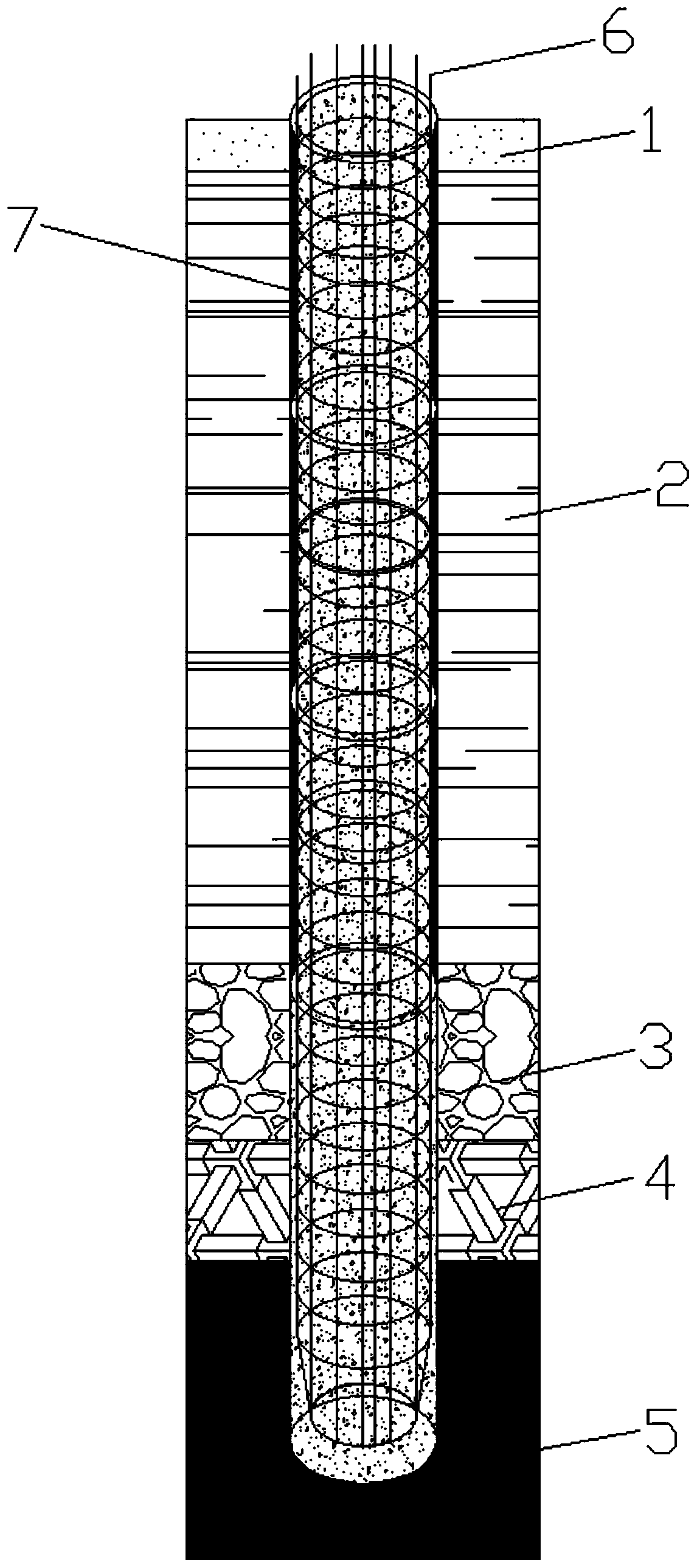
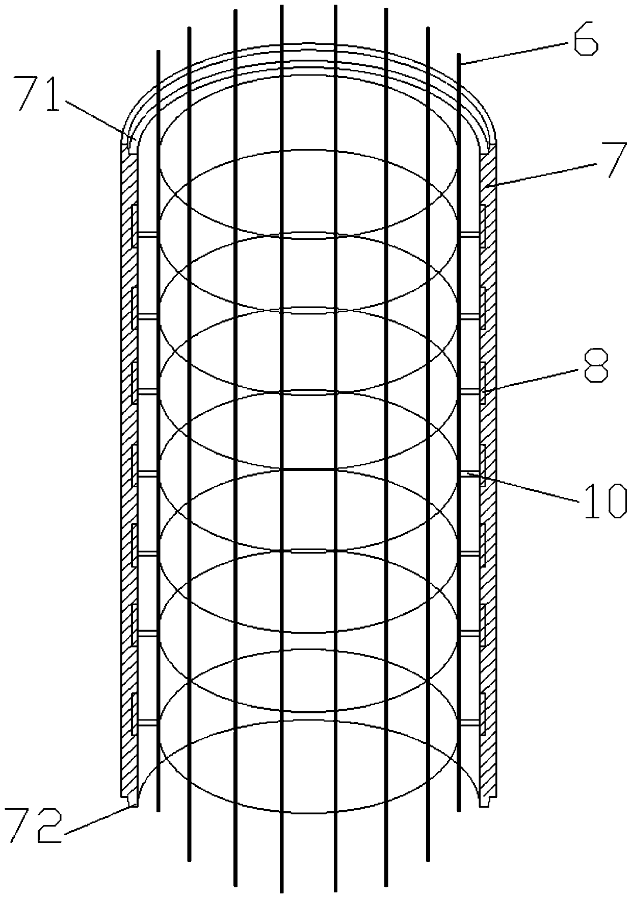
[0030] figure 1 It is a structural schematic diagram of the bored pile involved in an embodiment of the present invention. In this embodiment, the bored cast-in-place pile is an end-bearing pile with a diameter of 2 meters and a pile length of 40 meters, and the groundwater level is below the bottom of the pile. The order from top to bottom in the figure is: Miscellaneous fill layer 1, 2 meters thick; Silt layer 2, 20 meters thick; Strongly weathered rock layer 3, 3 meters thick; Medium weathered rock layer 4, 8 meters thick; Slightly weathered rock layer 5, The thickness is 12 meters. figure 2 It is a schematic diagram of a partial cross-sectional structure of a bored pile involved in an embodiment of the present invention. figure 2 shows the section structure of a cement circular pipe and the structure of the pile reinforcement cage where the joint circular pipe is located.

[0031] Please refer to figure 1 and figure 2 , the bored cast-in-place pile in the present i...

Embodiment 2

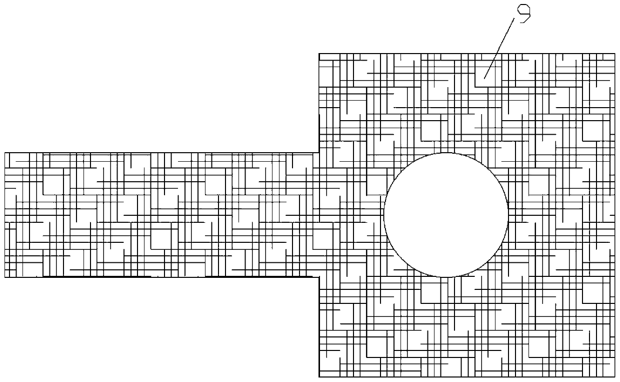
[0035] image 3 It is a schematic plan view of the construction platform involved in an embodiment of the present invention. Figure 4 It is a schematic flowchart of the construction method of the bored pile involved in one embodiment of the present invention.

[0036] In this embodiment, the construction method of the bored pile described in the first embodiment is introduced, and the construction method mainly includes the following steps:

[0037] Step S1: Carry out construction lofting on the pile site to determine the center of the pile site and the circumference line of the pile site.

[0038] Step S2: laying subgrade box slabs around the piles to form a construction platform 9 around the piles. The construction platform 9 is composed of a steel frame inserted in the mud layer and an upper roadbed box board, and each roadbed box board is connected together by a hinge. The middle of the construction platform 9 is where the pile holes are located, and one side of the co...


PUM


Abstract

The invention discloses a cast-in-situ bored pile and a construction method thereof. The cast-in-situ bored pile are applied to a geological environment with a sludge layer. Thin-shell concrete roundpipes are arranged at the periphery of a pile column reinforcement cage, so that the phenomenon of expanding or necking when the cast-in-situ bored pile is located at a part of the sludge layer and concrete is poured is avoided, the construction quality is improved, and the construction cost is reduced.

Description

technical field [0001] The invention relates to the technical field of pile foundation construction, in particular to a construction method for bored cast-in-situ piles applied in a mud layer environment. Background technique [0002] Bored pile is an important pile foundation in construction engineering and bridge engineering. During the construction process, the pile holes are firstly excavated and cleared by mechanical or artificial hole formation, then the steel cage is installed, and finally concrete is poured. Bored piles are subdivided into end-bearing piles and friction piles according to their stress modes. When constructing in a thicker silt layer geological environment, if friction piles are used, deeper pile holes are required; if end-bearing piles are used, the length of the pile holes entering the bedrock should also be greater than twice the pile diameter. In addition, it is very difficult to carry out pile construction in environments with thick silt layers ...

Claims


Application Information

Patent Timeline
Patent Type & Authority Applications(China)
IPC IPC(8): E02D5/38
CPCE02D5/38
Inventor 刘思谋刘思广
Owner MCC COMM CONSTR GRP CO LTD
Why Eureka
Try Eureka