
Closed loop grouting assembly, robot system and grouting method capable of achieving automatic control

A robotic system and closed-loop technology, which is applied to the processing of building components, building reinforcements, and building materials, can solve problems such as low grouting quality and efficiency, high requirements for construction workers' engineering experience, and poor working environment, etc., to improve The degree of automation and intelligence, the effect of ensuring stability and controllability, and saving manpower and material resources

Pending Publication Date: 2020-01-10
ANHUI UNIVERSITY OF ARCHITECTURE
View PDF0 Cites 6 Cited by
  • Summary
  • Abstract
  • Description
  • Claims
  • Application Information

AI Technical Summary

Problems solved by technology

At present, for the grouting process of prefabricated buildings, the grouting process used is mostly carried out by hand-held or low-automation equipment. This grouting process consumes a lot of manpower and material resources, and the grouting quality and efficiency are also low. And In the case that the components are not completely fixed, especially when the grouting operation is carried out at high altitude, the risk factor is high, the working environment is poor, and the engineering experience of the construction workers is required to be high, and even the grouting quality cannot be effectively guaranteed in some occasions , which undoubtedly hinders the process of industrialization of prefabricated buildings

Method used


Image

  • Closed loop grouting assembly, robot system and grouting method capable of achieving automatic control
  • Closed loop grouting assembly, robot system and grouting method capable of achieving automatic control
  • Closed loop grouting assembly, robot system and grouting method capable of achieving automatic control

Examples


Embodiment Construction

[0036] The technical scheme of the present invention will be described in further detail below in conjunction with the accompanying drawings and specific embodiments, so that those skilled in the art can better understand the present invention and implement it, but the examples given are not intended to limit the present invention.

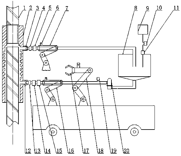
[0037] Such as figure 1 As shown, an automatically controlled closed loop grouting assembly, including a steel sleeve 2 and a grouting pipe, to figure 1 Take the direction as an example, the steel bar sleeve 2 is sleeved on the outer circumference of the steel bar 1, and the two are coaxially arranged, wherein, the steel bar sleeve 2 is provided with a slurry outlet 3 and a slurry inlet 12 from top to bottom, and the slurry outlet 3 and the inlet The grout opening 12 can be respectively provided with one, also can be provided with several, constitutes the grouting opening jointly. Wherein, the grout outlet 3 and the grout inlet 12 are respectivel...


PUM


Abstract

The invention disclosed a closed loop grouting assembly, robot system and grouting method capable of achieving automatic control. The method comprises the steps that 1, the grouting robot system roughly positions a slurry inlet and a slurry outlet through a BIM; 2, a robot moves to the working range of mechanical arms, and controls the mechanical arms to drive a grouting pipe to move; 3, after themechanical arms arrive at the portion nearby a grouting port, an electric control box detects the accurate position of the grouting port through cameras arranged on the mechanical arms, and then themechanical arms are driven to insert the grouting pipe into the grouting port; 4, grouting operation is started, and the grouting robot system judges whether to continue grouting or not by processingdata detected by a liquid level meter and a mud flow meter and controls starting and stopping of grouting; 5, after grouting is finished, the grouting robot system drives a slurry inlet mechanical armand a slurry outlet mechanical arm to return, and drives a blocking mechanical arm to clamp a plunger to block the slurry inlet and the slurry outlet. A lot of manpower and material resources are saved, the success rate of grouting is increased, and the stability and controllability of the grouting quality are guaranteed.

Description

technical field [0001] The invention relates to an automatically controlled closed loop grouting component, a robot system and a grouting method. Background technique [0002] Compared with the traditional "extensive" wet construction method, prefabricated buildings have great advantages in improving building information management, controlling building quality, reducing energy consumption, reducing production costs, and ensuring safe operations. At present, for the grouting process of prefabricated buildings, the grouting process used is mostly carried out by hand-held or low-automation equipment. This grouting process consumes a lot of manpower and material resources, and the grouting quality and efficiency are also low. And In the case that the components are not completely fixed, especially when the grouting operation is carried out at high altitude, the risk factor is high, the working environment is poor, and the engineering experience of the construction workers is re...

Claims


Application Information

Patent Timeline
Patent Type & Authority Applications(China)
IPC IPC(8): E04G21/04E04C5/16
CPCE04G21/04E04C5/165
Inventor 张润梅任瑞袁彬罗谷安毕利君李帅韦旺何玉
Owner ANHUI UNIVERSITY OF ARCHITECTURE
Features
  • Generate Ideas
  • Intellectual Property
  • Life Sciences
  • Materials
  • Tech Scout
  • Unparalleled Data Quality
  • Higher Quality Content
  • 60% Fewer Hallucinations
Learn More