
Oil extracting well mouth integrated device convenient to mount

An integrated device and oil well technology, applied in the direction of isolation device, earthwork drilling, wellbore/well parts, etc., can solve the problems of poor cleaning effect, spilling on the ground, low efficiency, etc., and achieve the effect of tight fit and easy scraping

Inactive Publication Date: 2020-01-10
魏海
View PDF4 Cites 4 Cited by
  • Summary
  • Abstract
  • Description
  • Claims
  • Application Information

AI Technical Summary

Problems solved by technology

[0002] When repairing and inspecting deep well pump construction due to downhole accidents in oil production wells, the oil pipe and sucker rod are first pulled out from the wellhead, and then the oil pipe and sucker rod are placed on the ground to be cleaned with a steam boiler. However, this measure not only The efficiency is low, and a large amount of oil stains and crude oil on the oil pipe and sucker rod are spilled on the ground during the cleaning process, causing serious environmental pollution, and because the length of the oil pipe is too long when it is lifted from the oil well, the oil stain will harden and be difficult to clean, and in the past The oil pipe cleaning method has poor cleaning effect and low cleaning efficiency, and requires a lot of labor. There is an urgent need for a more efficient, more environmentally friendly, and more automated construction technology to solve the above problems

Method used


Image

  • Oil extracting well mouth integrated device convenient to mount
  • Oil extracting well mouth integrated device convenient to mount
  • Oil extracting well mouth integrated device convenient to mount

Examples


Embodiment Construction

[0015] In order to make the purpose, technical solutions and advantages of the embodiments of the present invention clearer, the technical solutions in the embodiments of the present invention will be clearly and completely described below in conjunction with the drawings in the embodiments of the present invention. Obviously, the described embodiments It is a part of embodiments of the present invention, but not all embodiments. Based on the embodiments of the present invention, all other embodiments obtained by persons of ordinary skill in the art without creative efforts fall within the protection scope of the present invention.

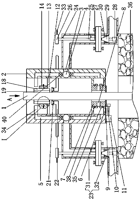
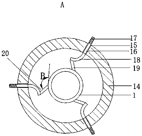
[0016]An oil production wellhead integrated device that is easy to install, as shown in the figure, includes an oil well 36, an oil pipe 1 is arranged inside the oil well 36, a fixed casing 2 is arranged on the outer side of the oil pipe 1, and high-pressure steam is fixedly connected to the left and right symmetrically on the outer side of the mid...


PUM


Abstract

The invention provides an oil extracting well mouth integrated device convenient to mount. The oil extracting well mouth integrated device convenient to mount comprises an oil well. An oil tube is arranged in the oil well, a fixing sleeve is arranged on the outer side of the oil tube, the outer side of the middle of the fixing sleeve is fixedly connected with high-pressure steam tubes in a left-and-right-symmetry manner, the high-pressure steam tubes are externally connected with a steam generator, an annular hole is formed in the tube wall of the middle of the fixing sleeve, multiple throughholes are formed in the bottom of an annular water tank, the positions, corresponding to the through holes in the bottom of the annular water tank, of the bottom of the annular water tank are connected with sludge extracting tubes, and the sludge extracting tubes are externally connected with sludge treatment equipment. High-pressure steam is inflated into the annular hole while the oil tube is extracted from a well mouth, thus, the oil tube is specially treated, oil dirt and dirt cannot be scattered on the ground at will, the oil dirt and the dirt on the oil tube are more automatically cleaned away, the efficiency is higher, the washing effect is better, multiple functions are achieved through one input action of the high-pressure steam, power sources are saved, and the oil extracting well mouth integrated device is more convenient to mount, dismount, carry and maintain.

Description

technical field [0001] The invention belongs to the field of oil production well head integrated devices, in particular to an oil production well head integrated device which is easy to install. Background technique [0002] When repairing and inspecting deep well pump construction due to downhole accidents in oil production wells, the oil pipe and sucker rod are first pulled out from the wellhead, and then the oil pipe and sucker rod are placed on the ground to be cleaned with a steam boiler. However, this measure not only The efficiency is low, and a large amount of oil stains and crude oil on the oil pipe and sucker rod are spilled on the ground during the cleaning process, causing serious environmental pollution, and because the length of the oil pipe is too long when it is lifted from the oil well, the oil stain will harden and be difficult to clean, and in the past The oil pipe cleaning method has poor cleaning effect and low cleaning efficiency, and requires a lot of ...

Claims


Application Information

Patent Timeline
IPC IPC(8): E21B37/00E21B37/02E21B36/00E21B41/02
CPCE21B36/00E21B37/00E21B37/02E21B41/02
Inventor 杨鹏胡欣欣贾莉吴凯郭文婷张斌朱学兵范伟东游晶晶蔡梦雪魏海李军
Owner 魏海
Learn More