Counter balance flange joint and application thereof

A balance method and reverse technology, which is applied in the directions of wind power generation, wind engine assembly, installation/supporting wind engine configuration, etc. It can solve the problems of large deviation of tower roundness, difficulty in guaranteeing weld quality, and heavy welding workload and other problems, to achieve the effect of reducing the deformation of the tower tube, facilitating mechanical flat welding, and reducing the amount of welding

Pending Publication Date: 2020-01-10
TONGJI UNIV ARCHITECTURAL DESIGN INST GRP CO LTD
View PDF1 Cites 5 Cited by
  • Summary
  • Abstract
  • Description
  • Claims
  • Application Information

AI Technical Summary

Problems solved by technology

However, the existing reverse balance flange has many welds, including multiple welds between the flange plate and the cylinder wall, the stiffened plate and the flange plate, and the stiffened plate and the cylinder wall. The welding workload of the factory is large, and the flange plate and the The weld seam of the cylinder wall is separated by the stiffening plate, which cannot be welded automatically, and manual welding is difficult, and the quality of the weld seam is difficult to guarantee; the flange only needs to pull the flexible tie rod in the transportation process, the bending rigidity is insufficient, and it is easy to deform, resulting in the The deviation of roundness is large, which will affect the tower installation

Method used


Image

  • Counter balance flange joint and application thereof
  • Counter balance flange joint and application thereof
  • Counter balance flange joint and application thereof

Examples


Embodiment

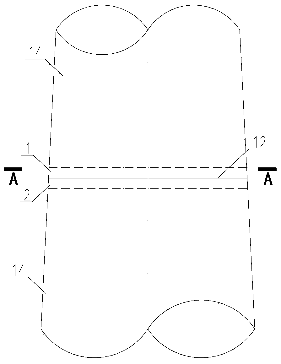
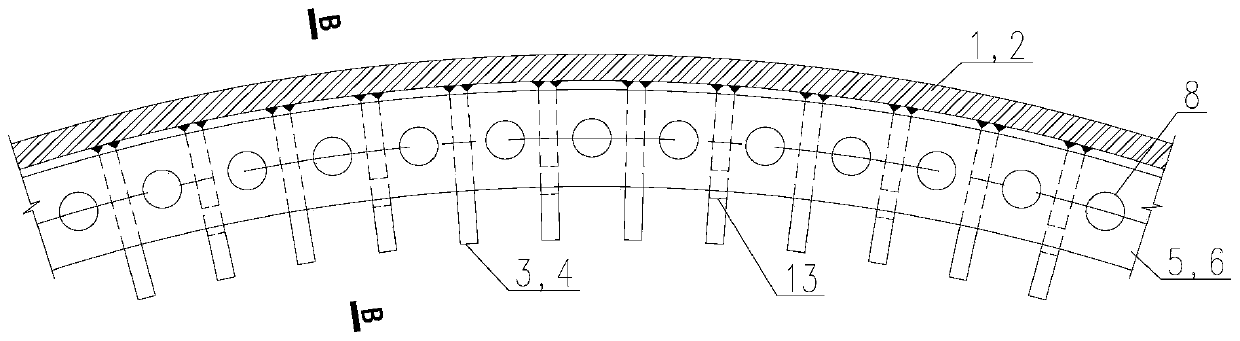
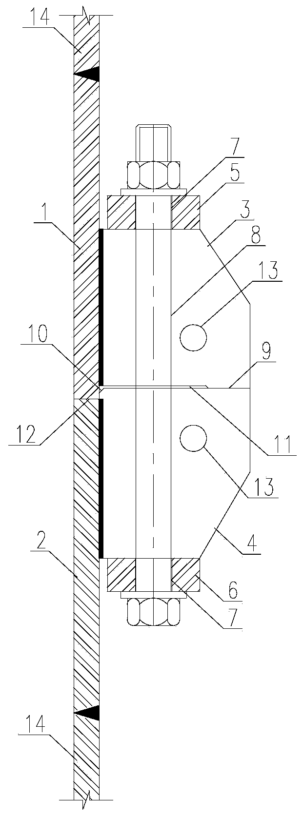
[0058] A reverse balanced flange joint, such as figure 1 As shown, the upper flange tower 1 and the lower flange tower 2 are included, and the upper flange tower 1 and the lower flange tower 2 are welded to the tower cylinder body 14. Such as figure 2 Shown and image 3 , The inner wall of the upper flange tower tube 1 is welded with a top stiffening plate 3, the inner wall of the lower flange tower tube 2 is welded with a guiding stiffening plate 4, and the upper surface of the top stiffening plate 3 is connected with an upper flange plate 5 through structural glue to guide the stiffening The lower surface of the plate 4 is connected with the lower flange plate 6 through structural glue, the upper flange plate 5 and the lower flange plate 6 are provided with bolt holes 7, and the high-strength bolt 8 penetrates the upper flange plate 5 and the lower flange through the bolt holes 7 The plate 6 connects the upper flange tower 1 and the lower flange tower 2; the top stiffening pl...


PUM


Abstract

The invention relates to a counter balance flange joint, which includes an upper flange tower and a lower flange tower, wherein a propping stiffening plate is welded on the inner wall of the upper flange tower; a guiding stiffening plate is welded on the inner wall of the lower flange tower; an upper flange plate is connected with the upper surface of the propping stiffening plate through a structural adhesive; the lower surface of the guiding stiffening plate is connected with a lower flange plate through a structural adhesive; bolt holes are formed in the upper flange plate and the lower flange plate; high-strength bolts penetrate through the upper flange plate and the lower flange plate through the bolt holes, so as to connect the upper flange tower with the lower flange tower; mountingholes are formed in the propping stiffening plate and the guiding stiffening plate respectively; connecting rods clamped with the corresponding stiffening plates are arranged inside the mounting holes; the two connecting rods are fastened and connected with annular auxiliary mechanisms arranged on the inner sides of the propping stiffening plate and the guiding stiffening plate. Compared with theprior art, the counter balance flange joint has the advantages of low welding amount, simple machining technology, high tower anti-fatigue level and no deformation during transportation.

Description

Technical field [0001] The invention belongs to the technical field of wind power tower structure steel tower tube connection in structural engineering, and in particular relates to a steel tower tube straight-supported reverse balance flange connection node and its application. Background technique [0002] At present, wind turbines often use large-diameter steel pipe towers as supporting structures, and the performance of the connection nodes of the large-diameter steel towers is crucial to ensuring the normal operation of the wind turbines. [0003] The thickness of the flange plate of the traditional forged flange is relatively large. The end face of the entire flange plate is milled flat. The workload is large, it is difficult to process, and the cost is high. The connecting bolts are easy to loose under the fatigue load. The existing reverse balance flange (ZL200920291676. 5. ZL201120088100.6 and ZL201620467194.0) include the "reverse" flange plate and the stiffening plate se...

Claims


Application Information

Patent Timeline
IPC IPC(8): F03D13/20F03D13/10B23P15/00
CPCF03D13/20F03D13/10B23P15/00B23P2700/11Y02E10/728Y02E10/72
Inventor 何敏娟何桂荣马人乐
Owner TONGJI UNIV ARCHITECTURAL DESIGN INST GRP CO LTD
Why Eureka
Try Eureka