Engine test bench water temperature control system

A test bench and water temperature control technology, applied in control/regulation systems, temperature control, non-electric variable control, etc., can solve the problems of low service life of resistance heaters, lagging equipment control temperature, and affecting the efficiency of rapid heat engines, etc. Achieve the effects of eliminating water temperature control fluctuations, low maintenance costs, and reducing energy consumption

Pending Publication Date: 2020-01-10
GUANGZHOU AUTOMIBILE GRP MOTOR
View PDF0 Cites 0 Cited by
  • Summary
  • Abstract
  • Description
  • Claims
  • Application Information

AI Technical Summary

Problems solved by technology

The current water temperature control system of the engine test bench mainly has the following problems: 1) The water temperature controller (proportional valve) is usually installed near the water inlet and outlet of the heat exchanger. It is installed at a position 2 meters away from the engine, and the temperature point that the equipment actually requires to control is the position of the engine water outlet. This installation distance directly leads to a lag in the temperature control of the equipment, and large fluctuations in water temperature control; 2) The existing water temperature control system uses The most important thing is that the embedded resistance heater heats the coolant, the loss of heating energy consumption is large, and the speed is slow, which affects the efficiency of the fast heating engine. In addition, due to the low service life of the resistance heater, the maintenance cost is high, and it needs to be removed and discharged when repairing and replacing. Cooling liquid, low efficiency; 3) The existing water temperature control system uses a high-level rehydration exhaust tank to exhaust the pipeline, but due to the complexity of the pipeline and the fast flow rate, the air bubbles often cannot be completely discharged through the exhaust port, while the gas Mixed in the water channel, it will cause fluctuations in temperature, resulting in low efficiency in controlling water temperature. image 3 shown

Method used


Image

  • Engine test bench water temperature control system
  • Engine test bench water temperature control system
  • Engine test bench water temperature control system

Examples


Embodiment 1

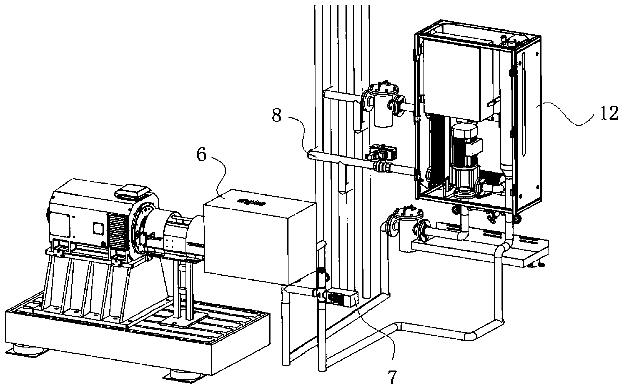
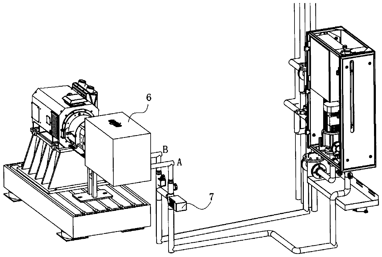
[0032] Such as figure 1 , 2 , 4, the present embodiment provides a water temperature control system for an engine test bench, including PLC1, a circulation loop and a fixed cabinet 12, the circulation loop includes a water pump 2, a heating device 3, a heat exchanger 4, and a liquid replenishment pipe 5, The water pump 2, the heating device 3, the heat exchanger 4, and the liquid replenishment pipe 5 are sequentially connected to each other, and the PLC 1 is electrically connected to all components of the circulation loop and controlled centrally.

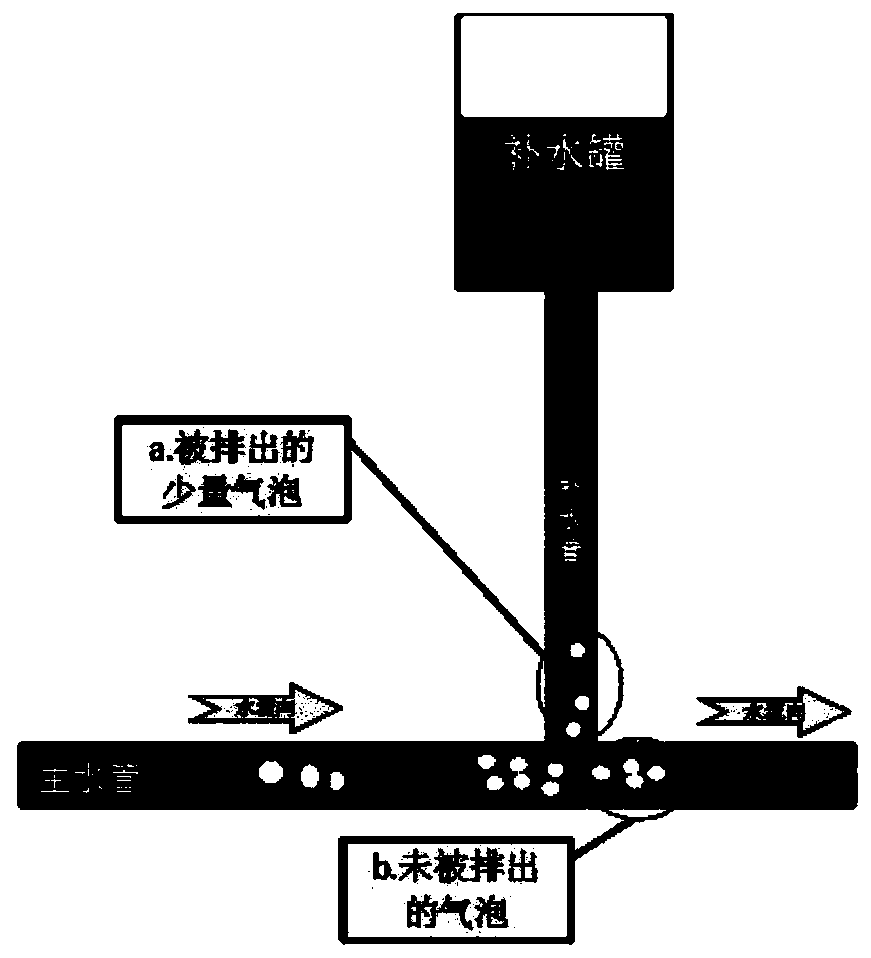
[0033] Specifically, the water pump 2 is used to increase the water pressure and promote the circulation of the water flow; the heating device 3 is used to heat the water flow; the heat exchanger 4 is used to supplement cold water and assist the temperature change of the water flow; the liquid replenishment pipe 5 is used to discharge the water flow Air bubbles in the tank, and replenish the engine 6 liquid level loss, directly t...


PUM


Abstract

The invention relates to the technical field of engine test equipment and more specifically relates to an engine test bench water temperature control system. The system comprises a PLC and a circulation loop. The circulation loop comprises a water pump, a heating device, a heat exchanger and a liquid supplementing pipe. The water pump, the heating device, the heat exchanger and the liquid supplementing pipe are sequentially communicated through pipelines, the circulation loop is further provided with an end A and an end B which are used for being connected with an engine water inlet and an engine water outlet, the end A is located on a water outlet side of the liquid supplementing pipe, and the end B is located on a water inlet side of the water pump. The PLC is electrically connected witheach part of the circulation loop and is controlled in a centralized manner. The circulation loop further comprises temperature control proportional valves used for adjusting the water temperature inreal time, and the temperature control proportional valves are arranged at a water inlet and a water outlet of the engine, water flow sequentially flows through the water pump, the heating device, the heat exchanger and the liquid supplementing pipe, enters the engine from the end A, then flows out from the end B, and enters the water pump again to circularly flow.

Description

technical field [0001] The present invention relates to the technical field of engine test equipment, and more specifically, to a water temperature control system of an engine test bench. Background technique [0002] The water temperature control system of the engine test bench is mainly used to control the temperature of the engine coolant during the bench test to maintain the target temperature T1 interval. The current water temperature control system of the engine test bench mainly has the following problems: 1) The water temperature controller (proportional valve) is usually installed near the water inlet and outlet of the heat exchanger. It is installed at a position 2 meters away from the engine, and the temperature point that the equipment actually requires to control is the position of the engine water outlet. This installation distance directly leads to a lag in the temperature control of the equipment, and large fluctuations in water temperature control; 2) The ex...

Claims


Application Information

Patent Timeline
Patent Type & Authority Applications(China)
IPC IPC(8): G05D23/20
CPCG05D23/20
Inventor 唐新和夏承睿李祖艺许华光韦健谢晓东刘念李伟健
Owner GUANGZHOU AUTOMIBILE GRP MOTOR
Why Eureka
Try Eureka