Semiconductor device structure and method of forming the same

A device structure and semiconductor technology, applied in the fields of semiconductor devices, semiconductor/solid-state device manufacturing, electrical components, etc., can solve problems such as affecting the on-resistance of devices, increasing switching losses, and unfavorable promotion and utilization.

Active Publication Date: 2020-03-17
INVENTCHIP TECH CO LTD
View PDF2 Cites 0 Cited by
  • Summary
  • Abstract
  • Description
  • Claims
  • Application Information

AI Technical Summary

Problems solved by technology
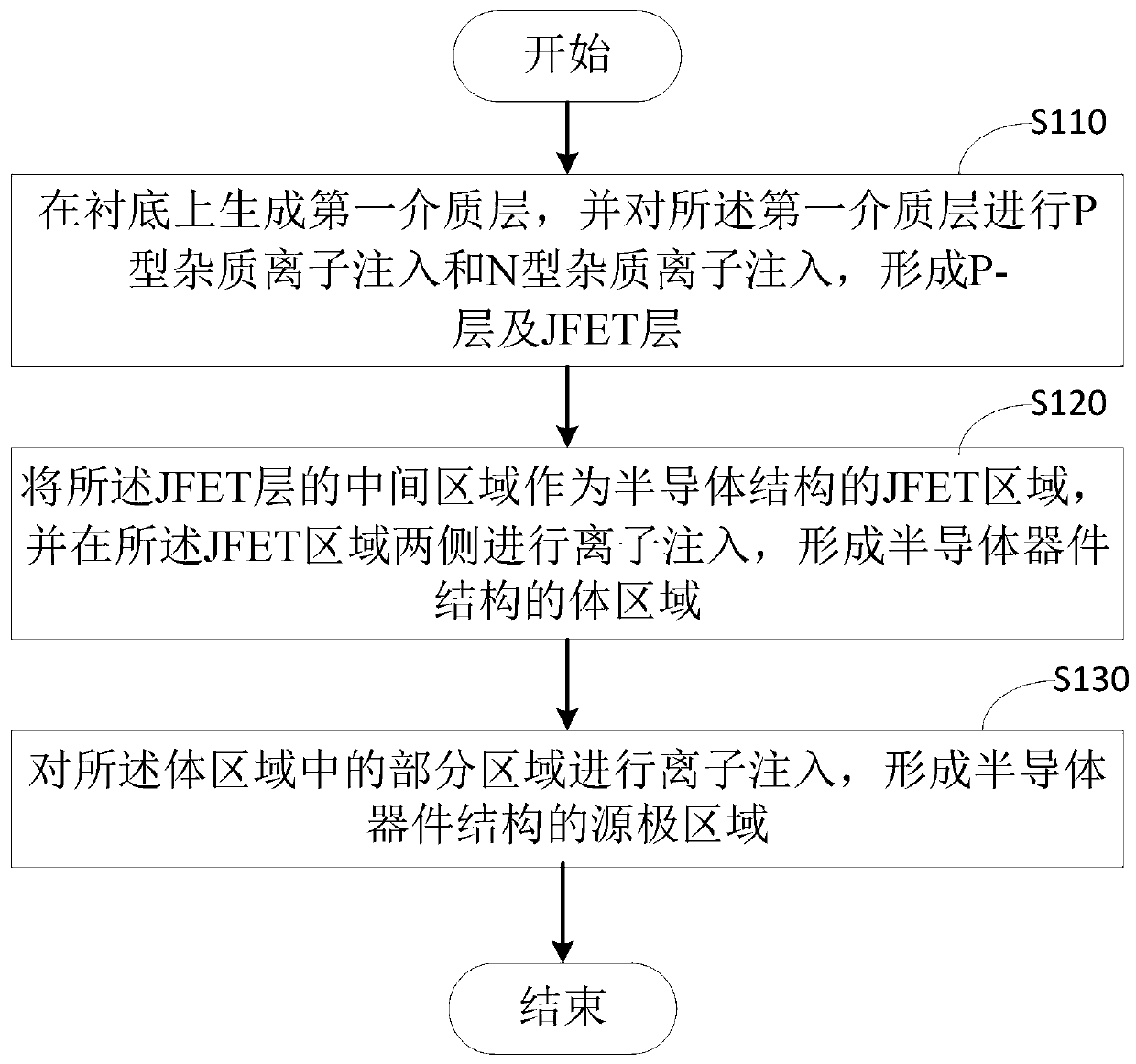
[0002] The traditional planar silicon carbide metal oxide semiconductor field effect transistor (Planar SiC MOSFET, such as vertical double diffused metal oxide transistor VDMOS) has a large device size, which affects the characteristic on-resistance of the device, which will increase the switching loss, resulting in The performance of the device is poor, and the cost of traditional planar silicon carbide devices is high, which is not conducive to popularization and utilization

Method used


Image

  • Semiconductor device structure and method of forming the same
  • Semiconductor device structure and method of forming the same
  • Semiconductor device structure and method of forming the same

Examples


Embodiment Construction

[0033] Various exemplary embodiments, features and aspects of the present disclosure will be described in detail below with reference to the accompanying drawings. The same reference numbers in the figures denote elements that have the same or similar functions. While various aspects of the embodiments are shown in the drawings, the drawings are not necessarily drawn to scale unless otherwise indicated.

[0034] The word "exemplary" is used exclusively herein to mean "serving as an example, embodiment, or illustration." Any embodiment described herein as "exemplary" is not necessarily to be construed as preferred or advantageous over other embodiments.

[0035] In addition, in order to better illustrate the present disclosure, numerous specific details are given in the following detailed description. It will be understood by those skilled in the art that the present disclosure may be practiced without certain specific details. In some instances, methods, means, components a...


PUM

PropertyMeasurementUnit
thicknessaaaaaaaaaa
thicknessaaaaaaaaaa
thicknessaaaaaaaaaa

Abstract

The disclosure relates to a semiconductor device structure and a forming method thereof. The method comprises the steps: generating a first dielectric layer on a substrate, performing P type impurityion implantation and N type impurity ion implantation on the first dielectric layer to form a P-layer and a JFET layer; taking the middle region of the JEFT layer as a JFET region of a semiconductor device structure, and performing ion implantation on two sides of the JEFT region to form a body region of the semiconductor device structure; and performing ion implantation on the part of the body region to form a source region of the semiconductor device structure. According to the embodiment of the invention, the JFET region is arranged at the semiconductor device structures, so that the characteristic conduction resistance of the semiconductor device is reduced and thus the conduction speed is increased and the switching power loss is reduced. Moreover, because the P-region is arranged atthe JFET region, the gate oxidation reliability of the device can be improved, the gate-drain capacitance of the device can be effectively reduced, and the switching power loss can be further reduced.

Description

technical field [0001] The present disclosure relates to the technical field of semiconductor processes, and in particular, to a semiconductor device structure and a method for forming the same. Background technique [0002] The traditional planar silicon carbide metal-oxide-semiconductor field-effect transistor (Planar SiC MOSFET, such as vertical double-diffused metal oxide transistor VDMOS) has a large device size, which affects the characteristic on-resistance of the device, which increases switching losses, resulting in The device performance is poor, and the traditional planar silicon carbide device has a high cost, which is not conducive to popularization and utilization. SUMMARY OF THE INVENTION [0003] In view of this, the present disclosure proposes a method for generating a semiconductor device structure, the method comprising: [0004] A first dielectric layer is formed on the substrate, and P-type impurity ion implantation and N-type impurity ion implantatio...

Claims


Application Information

Patent Timeline
Patent Type & Authority Patents(China)
IPC IPC(8): H01L21/336H01L29/78
CPCH01L29/66712H01L29/7802
Inventor 黄海涛张永熙陈伟
Owner INVENTCHIP TECH CO LTD
Why Eureka
Try Eureka