
Groove type high-power MOS device and manufacturing method thereof

A MOS device and high-power technology, applied in the field of trench type high-power MOS devices and their manufacturing, can solve the effect of limiting the withstand voltage and the reliability of the withstand voltage, limit the withstand voltage effect of the MOS device, and reduce the on-resistance of the device. and other problems, to achieve the effect of reducing the characteristic on-resistance, enhancing the reliability of the withstand voltage, and improving the withstand voltage capability.

Active Publication Date: 2011-05-11
WUXI NCE POWER
View PDF4 Cites 0 Cited by
  • Summary
  • Abstract
  • Description
  • Claims
  • Application Information

AI Technical Summary

Problems solved by technology

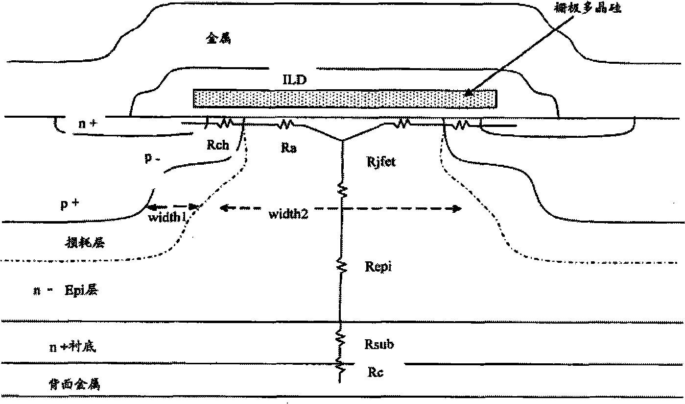
[0004] 1. It greatly restricts the integration of cells in a unit area, thus limiting the reduction space of the characteristic on-resistance of the device
[0005] 2. Between the two channels below the gate oxide, there is a junction field effect transistor on-resistance (JFET resistance) due to parasitic, and in the planar power MOS device, this part of the resistance occupies the entire device on-resistance More than 15%, so it becomes another important reason for limiting the on-resistance of device characteristics
[0008] 1. The depth of the second conductivity type well area in the cell area and the terminal protection area is the same, which limits the effect of withstand voltage and the reliability of withstand voltage
[0009] 2. The manufacturing process of the second conductivity type well region in the cell region and the terminal protection region is the same, which limits the adjustment of the process window for the second conductivity type well region in the cell region or the second conductivity type well region in the voltage division protection region. , thus limiting the withstand voltage effect of the MOS device

Method used


Image

  • Groove type high-power MOS device and manufacturing method thereof
  • Groove type high-power MOS device and manufacturing method thereof
  • Groove type high-power MOS device and manufacturing method thereof

Examples


Embodiment Construction

[0038] The present invention will be further described below in conjunction with specific drawings and embodiments.

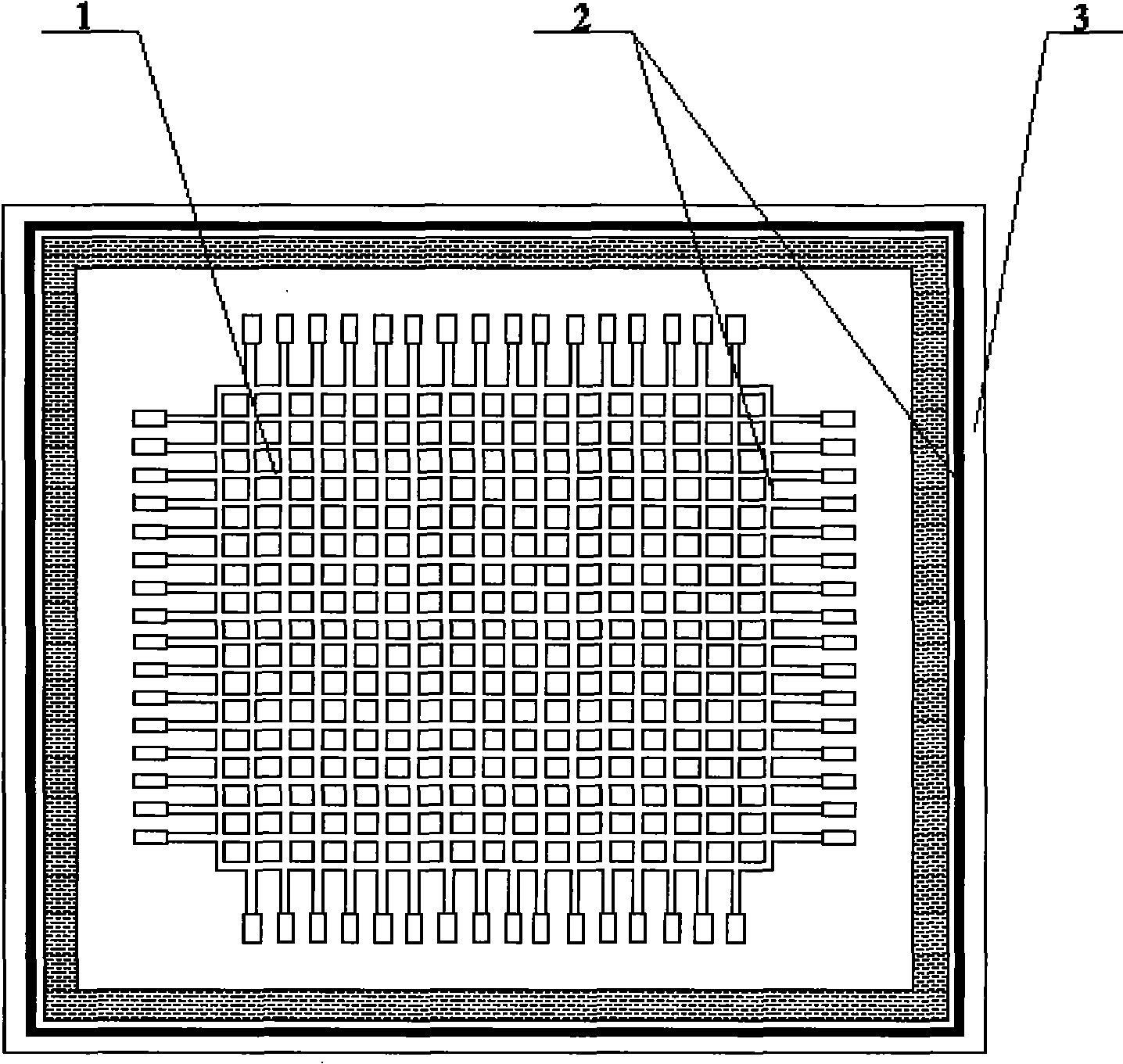
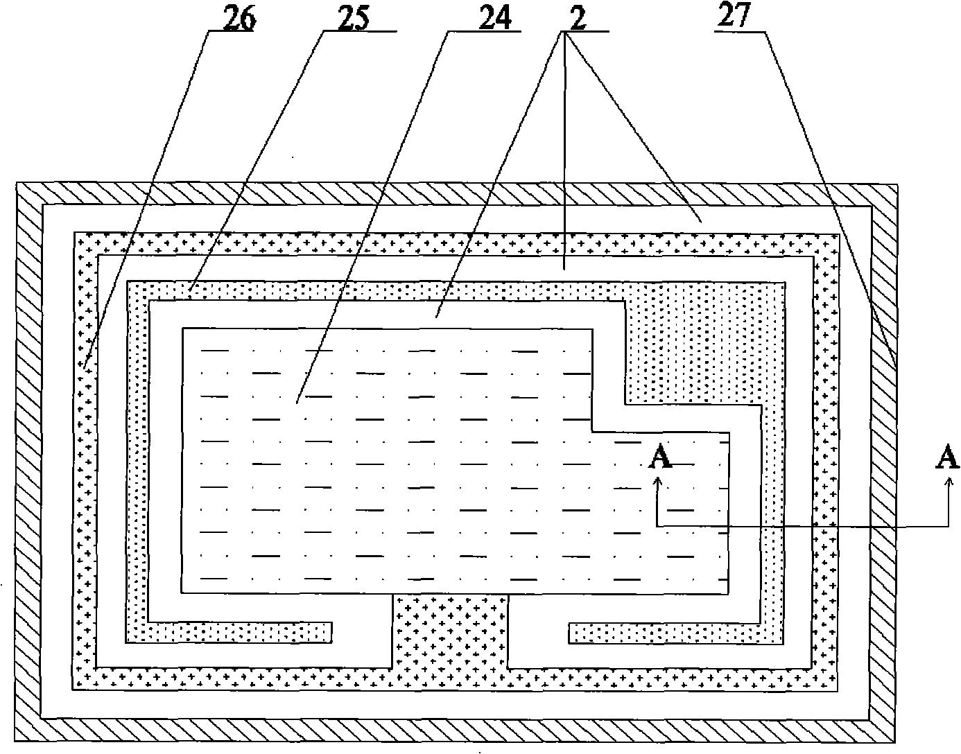
[0039] Such as Figure 2-9 As shown: taking an N-type MOS device as an example, the present invention includes a cell area 1, a voltage dividing protection area 2, a cut-off protection area 3, a photoresist 4, a P well layer 5 in the voltage dividing area, a field oxide layer 6, and a gate terminal 7. N+ substrate 8, N-type epitaxial layer 9, N+ implantation region 10, insulating gate oxide layer 11, conductive polysilicon 12, gate terminal trench 13, cell trench 14, stop trench 15, contact hole filling Metal 16, insulating dielectric layer 17, first ohmic contact hole 18, second ohmic contact hole 19, third ohmic contact hole 20, fourth ohmic contact hole 21, fifth ohmic contact hole 22, cut-off protection region P well layer 23 , a source metal 24 , a gate metal 25 , a third metal 26 , a fourth metal 27 and a P-well layer 28 in the cell region.

[0040] f...


PUM


Abstract

The invention relates to an MOS device and a manufacturing method thereof, in particular to a groove type high-power MOS device and the manufacturing method thereof. According to the technical scheme provided by the invention, on the overlook plane of the MOS device, the groove type high-power MOS device comprises a cellular area on a semi-conductive substrate and a terminal protection structure,the cellular area is arranged in the central area of the semi-conductive substrate; the periphery of the cellular area is provided with the terminal protection structure which comprises a partial pressure protection area at the inner circle and a cutoff protection area at the outer circle; by deepening the depth and the concentration of a second conductive type layer in the partial pressure protection area, the peripheral curvature in the well region of the partial pressure protection area is increased, thus inhibiting electric field concentration and increasing the withstand voltage. The groove type high-power MOS device and the manufacturing method have the advantages of low resistance, high voltage-resistant capacity, high reliability, simple process and low cost.

Description

technical field [0001] The invention relates to a MOS device and a manufacturing method thereof, in particular to a trench type high-power MOS device and a manufacturing method thereof. Background technique [0002] The specific on-resistance (Specific Rdson) and breakdown characteristics of high-power MOS devices are two important aspects that determine product performance. On the premise of not affecting device performance, cost reduction is one of the core contents of design and manufacturing. At present, Chinese patent CN101459084A discloses a "planar double-diffused metal oxide semiconductor device and its manufacturing method", which uses planar double-diffusion technology to manufacture power MOS devices, and reduces the on-resistance of the device through JFET injection. [0003] Such as figure 1 Shown: is the structure of the power MOS device disclosed in Chinese patent CN101459084A, the conduction channel is formed by the lightly doped second conductivity type wel...

Claims


Application Information

Patent Timeline
Patent Type & Authority Patents(China)
IPC IPC(8): H01L29/78H01L21/336
Inventor 朱袁正叶鹏丁磊冷德武
Owner WUXI NCE POWER
Learn More