Current backflow prevention circuit and intelligent door lock system

An intelligent door lock and anti-backflow technology, applied in circuit devices, emergency protection circuit devices, electrical components, etc., can solve problems such as energy loss, damage to electronic equipment, and large loss, and achieve the effect of reducing loss.

Pending Publication Date: 2020-01-10
SHENZHEN OURUIBO ELECTRONICS
View PDF0 Cites 6 Cited by
  • Summary
  • Abstract
  • Description
  • Claims
  • Application Information

AI Technical Summary

Problems solved by technology

[0003] However, when multiple power supplies are used to supply power to electronic equipment, due to the different potentials of each power supply, current backflow will occur between the power supply with high potential and the power supply with low potential, thus causing damage to the electronic equipment
[0004] In the prior art, the power supply system composed of multiple power supplies is generally divided by using the reverse cut-off characteristic of the diode to prevent the current backflow in the circuit. However, when the diode is in the forward conduction state, due to the forward conduction voltage drop The existence of the diode will cause a certain amount of energy loss. In low-power products, when there is a current peak, such as the starting current of the motor, the current emitted by the communication module, a relatively large loss will be generated at both ends of the diode.

Method used


Image

  • Current backflow prevention circuit and intelligent door lock system
  • Current backflow prevention circuit and intelligent door lock system
  • Current backflow prevention circuit and intelligent door lock system

Examples


Embodiment Construction

[0021] In order to make the purposes, technical solutions and advantages of the embodiments of the present application clearer, the technical solutions in the embodiments of the present application will be clearly and completely described below in conjunction with the drawings in the embodiments of the present application. Obviously, the described embodiments It is a part of the embodiments of this application, not all of them. The components of the embodiments of the application generally described and illustrated in the figures herein may be arranged and designed in a variety of different configurations.

[0022] Accordingly, the following detailed description of the embodiments of the application provided in the accompanying drawings is not intended to limit the scope of the claimed application, but merely represents selected embodiments of the application. Based on the embodiments in this application, all other embodiments obtained by persons of ordinary skill in the art w...


PUM


Abstract

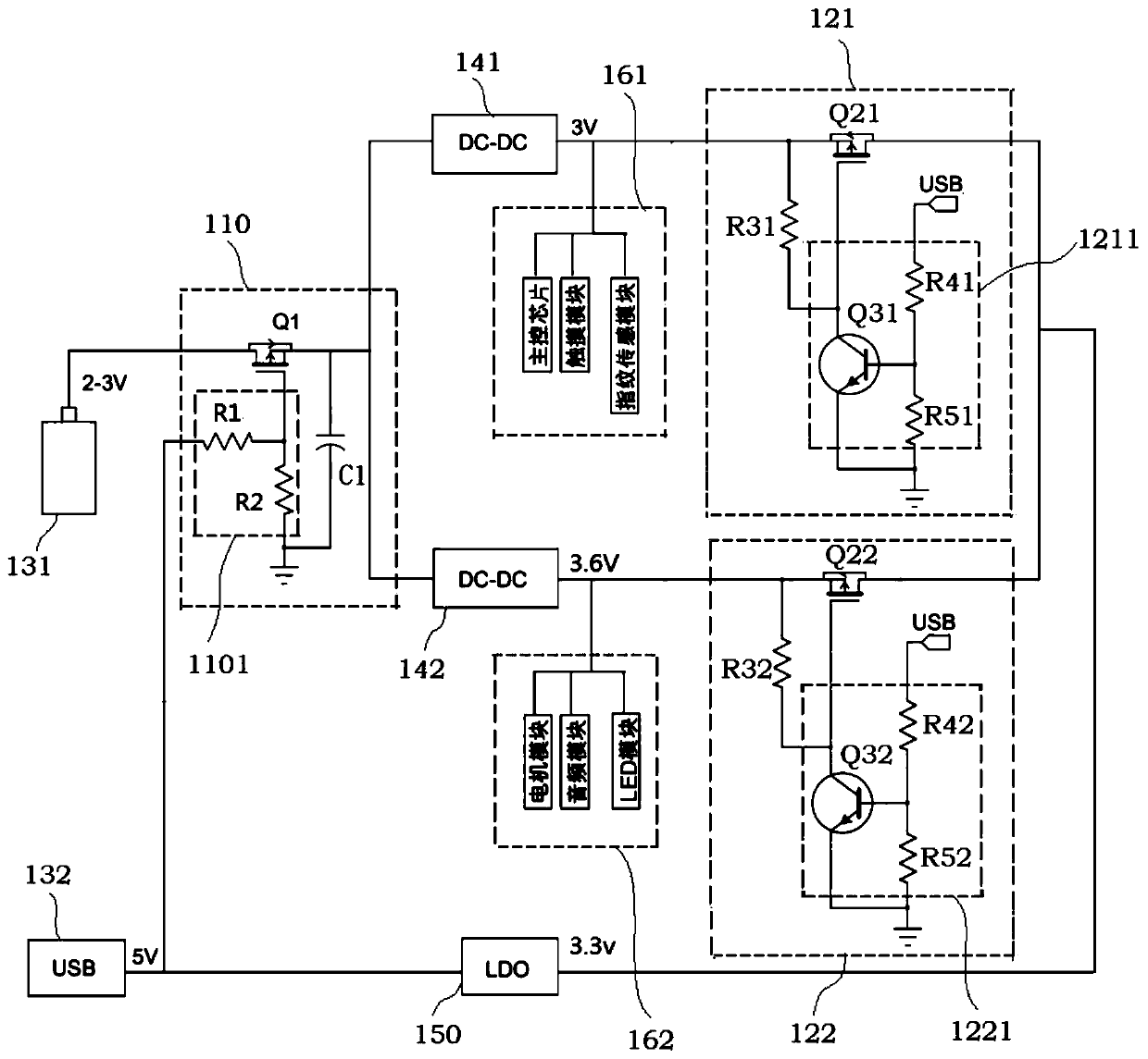
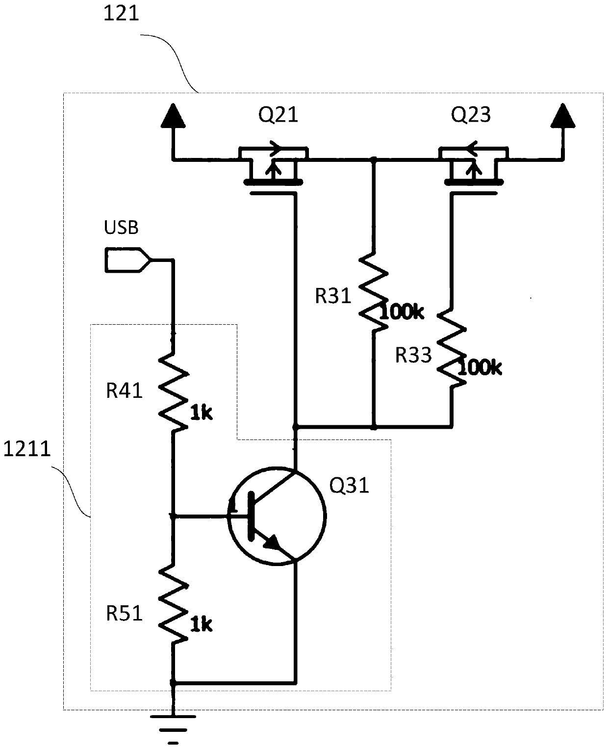
The embodiments of the invention provide a current backflow prevention circuit and an intelligent door lock system and belongs to the field of electronic equipment. The current backflow prevention circuit comprises a first current backflow prevention module, boost circuits and second current backflow prevention modules; the first current backflow prevention module comprises a first MOS transistorand a first control unit; each second current backflow prevention module comprises a second MOS transistor and a second control unit; the first current backflow prevention module is connected with a first power supply; the second current backflow prevention modules are connected with a second power supply; the first control unit can control the conduction or cut-off of the first MOS transistor according to the output voltage of the second power supply, so that backflow current can be prevented from being generated between the first power supply and the boost circuits; each second control unitcan control the conduction or cut-off of the corresponding second MOS transistor according to the output voltage of the second power supply, so that backflow current can be prevented from being generated between the second power supply and the boost circuits. With the current backflow prevention circuit and the intelligent door lock system of the invention adopted, current backflow caused by different potentials of multiple paths of power supplies can be avoided, energy consumption can be reduced, and the charging safety of equipment is ensured.

Description

technical field [0001] The present application relates to the technical field of electronic equipment, in particular to an anti-current backflow circuit and an intelligent door lock system. Background technique [0002] With the rapid development of science and technology, more and more electronic devices have entered people's lives. At present, most electronic devices, especially low-power electronic devices, can usually be powered by multiple power sources, thereby facilitating the use of the electronic devices by users. [0003] However, when multiple power supplies are used to supply power to electronic equipment, due to the different potentials of the power supplies, current backflow will occur between the power supply with high potential and the power supply with low potential, thus causing damage to the electronic equipment. [0004] In the prior art, the power supply system composed of multiple power supplies is generally divided by using the reverse cut-off charact...

Claims


Application Information

Patent Timeline
Patent Type & Authority Applications(China)
IPC IPC(8): H02H11/00H02J1/10H02J9/06
CPCH02H11/00H02H11/006H02J1/10H02J9/061
Inventor 陈煜平
Owner SHENZHEN OURUIBO ELECTRONICS
Why Eureka
Try Eureka