Stirring head with stirring needle with concave rotation contour

The technology of stirring needle and stirring head is applied in the field of friction stir welding, which can solve the problems of insufficient flow of softened material in the welding seam area, bad influence on the quality of welding seam, insufficient stirring and forging pressure, etc., and achieves simple and reliable structure, reduced volume, and increased The effect of compactness

Pending Publication Date: 2020-01-14
HUNAN JOINFRONT WELDING TECH
View PDF0 Cites 0 Cited by
  • Summary
  • Abstract
  • Description
  • Claims
  • Application Information

AI Technical Summary

Problems solved by technology

Ordinary stirring heads are generally conical or cylindrical in structure. During the welding process, especially in the friction stir welding of thick plates, it is easy to cause insufficient flow of softened materials in the weld zone and insufficient stirring forging pressure, which is not conducive to forming a good weld. seam, which has a certain adverse effect on the quality of the weld

Method used


Image

  • Stirring head with stirring needle with concave rotation contour
  • Stirring head with stirring needle with concave rotation contour
  • Stirring head with stirring needle with concave rotation contour

Examples


Embodiment 1

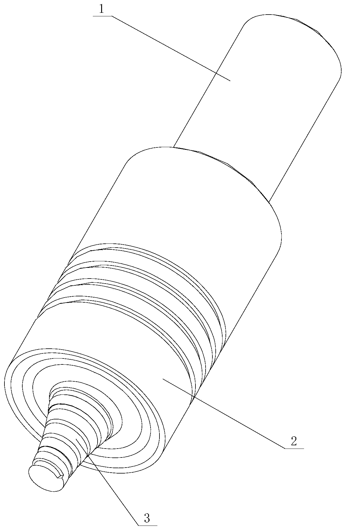
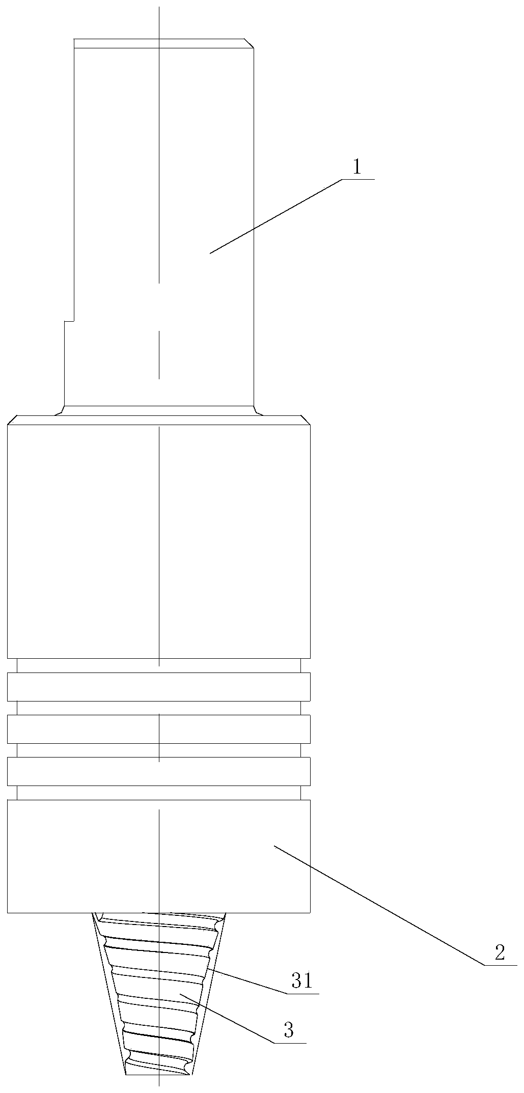
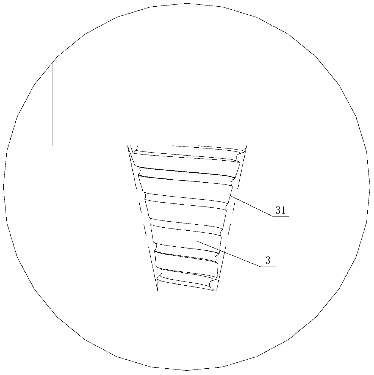
[0035] Figure 1 to Figure 4 It shows the first embodiment of the stirring head of the present invention, which is concave in the rotation profile of the stirring needle, including the clamping part 1, the shaft shoulder part 2 and the stirring needle 3 connected in sequence, and the peripheral side of the stirring needle 3 is provided with a Recess 31 for forging pressure. During welding, the clamping part 1 is used for clamping, the stirring pin 3 generates heat energy through rotational friction, and the shoulder part 2 is used to form forging. Compared with the traditional structure, the stirring head is provided with a concave portion 31 on the peripheral side of the stirring needle 3, that is, the peripheral side of the stirring needle 3 is concave, which increases the forging force in the inner depth direction, thereby increasing the density of the weld seam It is beneficial to increase the strength of the weld seam and improve the quality of the weld seam; at the same...

Embodiment 2

[0041] Such as Figure 5 As shown, the second embodiment of the concave stirring head with the rotation profile of the stirring needle of the present invention is basically the same as that of Embodiment 1, the only difference is that in this embodiment, the outer contour of the concave portion 31 is formed by multiple inner sections Concave arc lines are connected to form. In this structure, the peripheral outline of the concave portion 31 is composed of multiple curves, and the structure is simple and reliable.

Embodiment 3

[0043] Such as Figure 6 As shown, the third embodiment of the stirring head of the present invention with a concave shape of the stirring needle rotation profile, the stirring head is basically the same as that of Embodiment 1, the only difference is that in this embodiment, the peripheral contour of the concave portion 31 is concave The circular arc lines and oblique lines are connected. In this structure, the peripheral outline of the concave portion 31 is composed of a combination of curved and oblique lines, and the structure is simple and reliable.

[0044] In this embodiment, the arc line is close to the needle base 34 , and the oblique line is close to the needle tip 33 . Its structure is simple and easy to operate.


PUM


Abstract

The invention discloses a stirring head with a stirring needle with the concave rotation contour. The stirring head comprises a clamping part, a shaft shoulder part and the stirring needle which are sequentially connected, and a concave part for improving forging force in the depth direction is arranged on the peripheral side of the stirring needle. The stirring head has the advantages that the structure is simple and reliable, the forging force can be improved, the weld joint strength can be improved, and a good weld joint is formed.

Description

technical field [0001] The invention mainly relates to the friction stir welding technology, in particular to a stirring head with a concave-shaped rotating profile of a stirring needle. Background technique [0002] In the friction stir welding process, the interaction between the stirring head and the workpiece material generates heat, and the workpiece material around the stirring head is heated to a plasticized state to form a weld. The heat mainly includes the friction between the shaft shoulder and the stirring needle and the base material Heat generation and plastic deformation heat generated by stirring and extruding workpiece materials. During the friction stir welding process, the temperature field of the workpiece is unevenly distributed, showing the law that the temperature at the shaft shoulder of the stirring head is the highest and gradually decreases toward the end surface of the stirring pin. [0003] Stirring head is the core of friction stir welding techn...

Claims


Application Information

Patent Timeline
IPC IPC(8): B23K20/12
CPCB23K20/12B23K20/1255
Inventor 钟南李志明李贤清周长兴汤雨竹
Owner HUNAN JOINFRONT WELDING TECH
Why Eureka
Try Eureka