Broadband laser processing optical system capable of being modulated and processing method

A laser processing and optical system technology, applied in metal processing equipment, laser welding equipment, manufacturing tools, etc., can solve problems such as low efficiency and poor processing quality, and achieve the effect of improving flexibility, improving processing quality, and improving processing efficiency

Pending Publication Date: 2020-01-14
HUAZHONG UNIV OF SCI & TECH
View PDF9 Cites 8 Cited by
  • Summary
  • Abstract
  • Description
  • Claims
  • Application Information

AI Technical Summary

Problems solved by technology

[0004] Aiming at the defects of the prior art, the present invention proposes an adjustable broadband laser processing optical system a

Method used


Image

  • Broadband laser processing optical system capable of being modulated and processing method
  • Broadband laser processing optical system capable of being modulated and processing method
  • Broadband laser processing optical system capable of being modulated and processing method

Examples


Embodiment 1

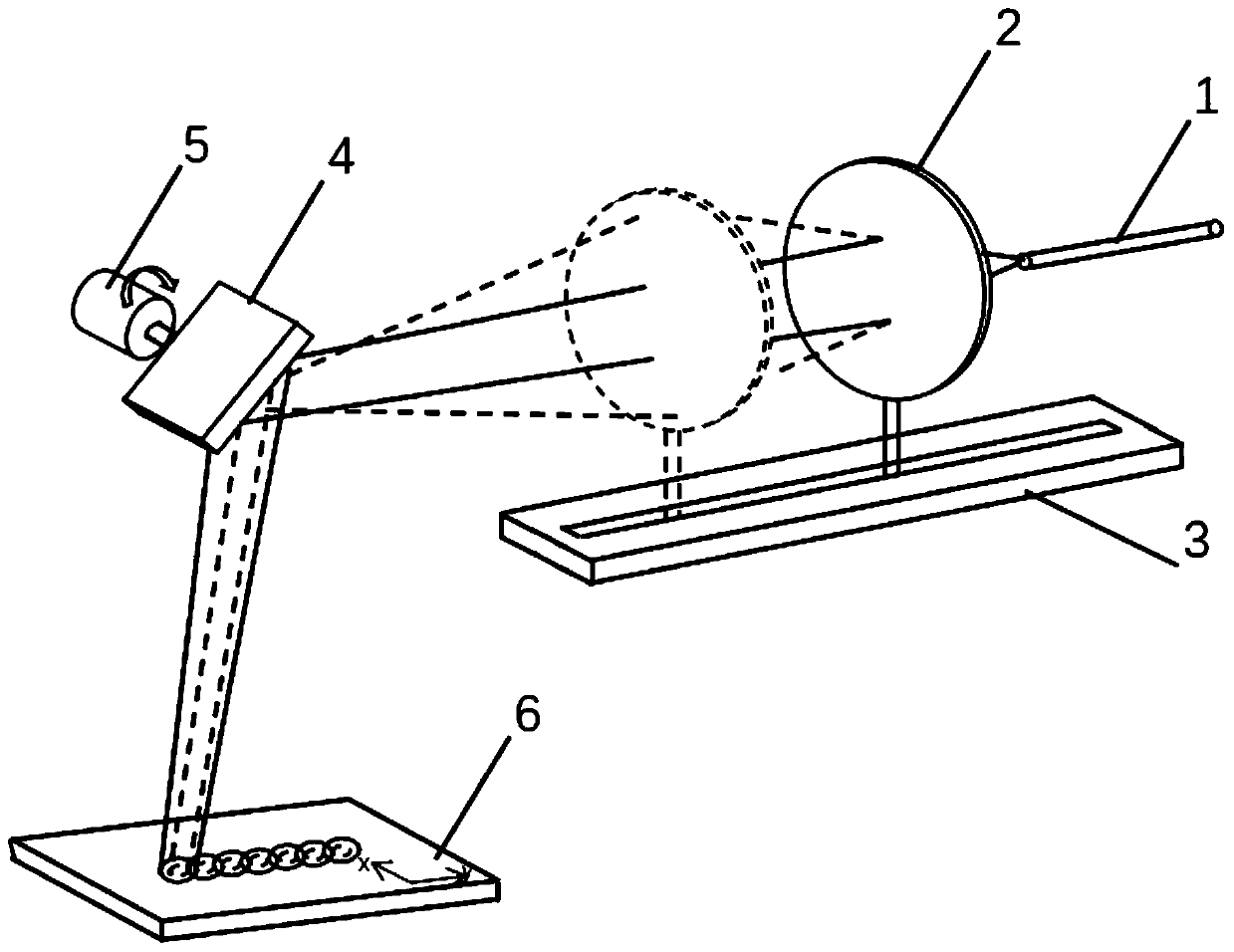
[0030] Such as figure 1 As shown, an adjustable broadband laser processing optical system provided by the embodiment of the present invention includes a fiber laser 1, a focusing lens 2, a first motor and a guide rail 3 for controlling the movement of the focusing lens 2, a vibrating mirror 4, and a driving vibrator. The second motor 5 and the working surface 6 of the mirror vibration. The beam emitted by the fiber laser 1 enters the focusing lens 2 at a certain divergence angle, and the beam is collimated and focused by the focusing lens 2 and then enters the vibrating mirror 4, and then is reflected to the working surface 6 by the vibrating mirror 4.

[0031] The focusing lens 2 is connected with the bracket on the guide rail, and is controlled by the first motor to move back and forth along the optical axis direction on the guide rail, so as to realize the effect of changing spots on the working surface 6 . The traditional laser processing optical system uses a combination...

Embodiment 2

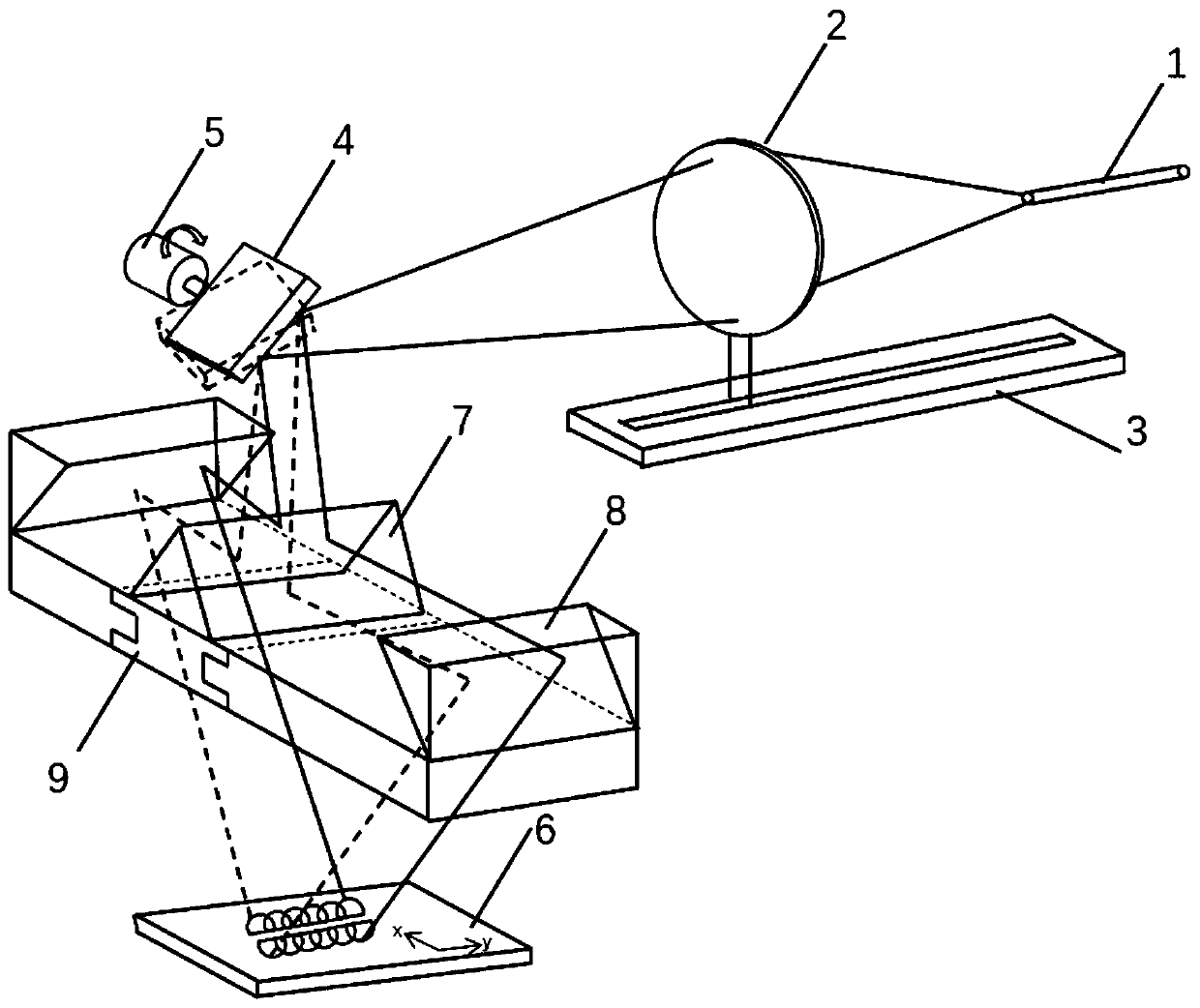
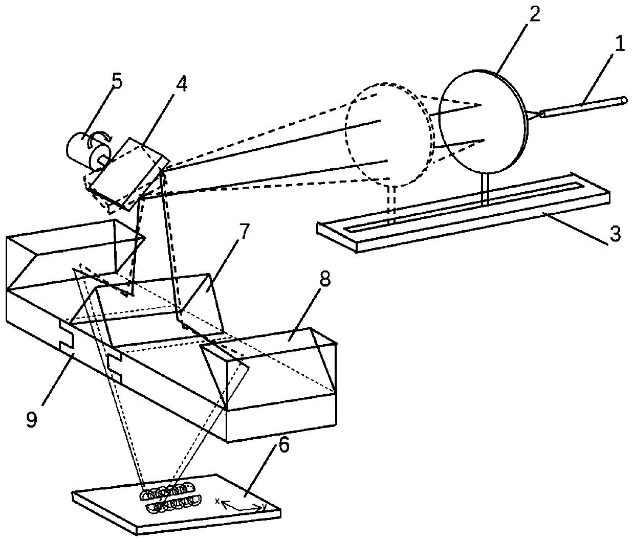
[0034] Such as figure 2 Another adjustable broadband laser processing optical system provided by the embodiment of the present invention includes a fiber laser 1, a focusing lens 2, a first motor and a guide rail 3 for controlling the movement of the focusing lens 2, a vibrating mirror 4, and a driving vibrating mirror Vibrating second motor 5, dichroic prism 7, reflector 8, sliding groove 9 and working surface 6 for controlling the position of dichroic prism 7, wherein dichroic prism 7, reflecting mirror 8, sliding groove for controlling the position of dichroic prism 7 9 form a spectroscopic device. The beam emitted by the fiber laser 1 enters the focusing lens 2 at a certain divergence angle. The beam is collimated and focused by the focusing lens 2 and then enters the galvanometer 4, and is reflected by the galvanometer 4 to the two beam-splitting facets of the beam-splitting prism 7. The beam is transmitted by the beam-splitting prism 7 After reflection and splitting, t...


PUM


Abstract

The invention discloses a broadband laser processing optical system capable of being modulated and a processing method, and belongs to the field of laser processing optical systems. The broadband laser processing optical system comprises a laser, a mobile focusing lens unit, a scanning vibrating mirror unit and a working surface, the mobile focusing lens unit comprises a focusing lens, a first motor and a guiding rail, the first motor controls the focusing lens to move along the guiding rail, the scanning vibrating mirror unit comprises a vibrating mirror, and a second motor, and the vibratingmirror is connected to the second motor; and the beam emitted by the laser is incident at a certain emission angle to the focusing lens, and the beam is incident to the vibrating mirror after collimating and focusing of the focusing lens and then reflected by the vibrating mirror, so that the beam is used for laser processing of a workpiece on the working surface. According to the broadband laserprocessing optical system, the size of a working spot can be quickly and sensitively adjusted, obvious advantages are achieved especially for a special-shaped or uneven processing surface, and the uniformity of processing and processing efficiency are further improved.

Description

technical field [0001] The invention belongs to the field of laser processing optical systems, and more specifically relates to an adjustable broadband laser processing optical system and method. Background technique [0002] Laser processing technology is a surface modification technology that uses high-energy lasers and nano-materials to carry out alloy strengthening treatment on various parts, which can significantly improve the wear resistance, corrosion resistance, heat resistance, and Oxidation and other engineering properties. In recent years, with the rapid development of industrialization and laser technology industry, laser processing has been widely used in direct molding and remanufacturing production processes as an effective method to improve the surface quality and service life of devices. [0003] The existing laser processing and forming systems mostly use optical elements to cut and reshape the laser beam. The function of the laser processing optical syste...

Claims


Application Information

Patent Timeline
IPC IPC(8): B23K26/064B23K26/082B23K26/70
CPCB23K26/0643B23K26/0648B23K26/0652B23K26/082B23K26/702
Inventor 秦应雄车昕刘晓东唐霞辉
Owner HUAZHONG UNIV OF SCI & TECH
Why Eureka
Try Eureka