A kind of reinforced lithium battery separator and its manufacturing method

A lithium battery separator and manufacturing method technology, applied in secondary batteries, battery pack components, circuits, etc., can solve the problems of thermal shrinkage, fall off, and affect the overall performance of the separator, achieve low thermal shrinkage, improve tensile strength, The effect of increasing the temperature difference

Active Publication Date: 2022-04-15
SHANGHAI ENERGY NEW MATERIALS TECH CO LTD
View PDF0 Cites 0 Cited by
  • Summary
  • Abstract
  • Description
  • Claims
  • Application Information

AI Technical Summary

Problems solved by technology

[0004] In order to improve the safety of the lithium-ion battery separator, the most common method is to apply ceramic slurry coating to the polymer separator or to prepare a multi-layer separator by co-extrusion technology. The coating process is coated on the surface of the basic separator. Ceramic particles may also fall off during battery use, causing local thermal shrinkage of the separator and affecting the overall performance
The second method is to use multi-layer co-extrusion technology, which requires special equipment for production. The multi-layer co-extrusion process is complicated, and the performance of the diaphragm is not easy to control.

Method used


Image

  • A kind of reinforced lithium battery separator and its manufacturing method
  • A kind of reinforced lithium battery separator and its manufacturing method
  • A kind of reinforced lithium battery separator and its manufacturing method

Examples


Embodiment 1

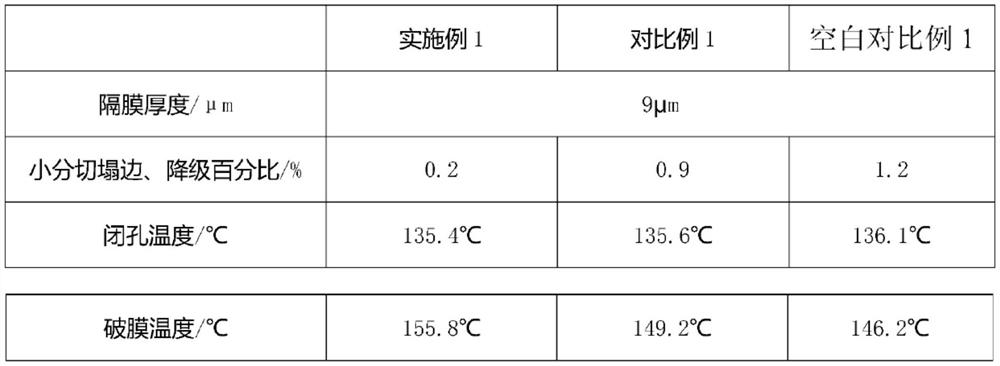
[0035] Example 1 Raw material ratio: 80 parts by weight of high molecular weight polyethylene, with a viscosity average molecular weight of 1 million; 20 parts by weight of high molecular weight polypropylene, with a viscosity average molecular weight of 1.2 million; 3 parts by weight of ethylene-propylene copolymer, with an ethylene content of 52 %, Mooney viscosity 83; 0.1 parts by weight of antioxidant is 0.06 parts by weight of antioxidant 1010 and 0.04 parts by weight of antioxidant 168 compound;

Embodiment 2

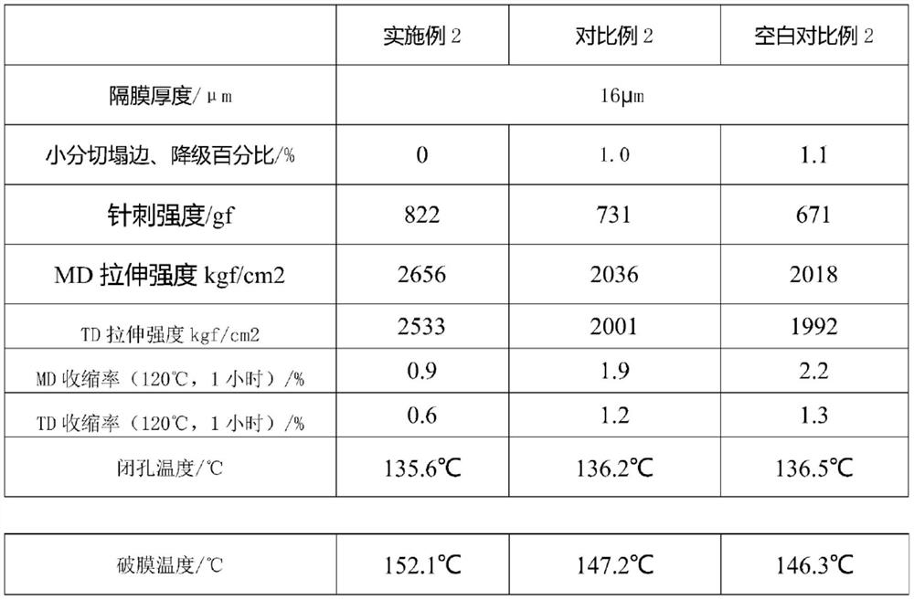
[0045] Example 2 Raw material ratio: 78 parts by weight of high molecular weight polyethylene, with a viscosity average molecular weight of 600,000; 22 parts by weight of high molecular weight polypropylene, with a viscosity average molecular weight of 1 million; 3 parts by weight of ethylene-propylene copolymer, with an ethylene content of 52 %, Mooney viscosity 83; 0.1 parts by weight of antioxidant is 0.06 parts by weight of antioxidant 1010 and 0.04 parts by weight of antioxidant 168 compound; performance comparison is shown in Table 2:

Embodiment 3

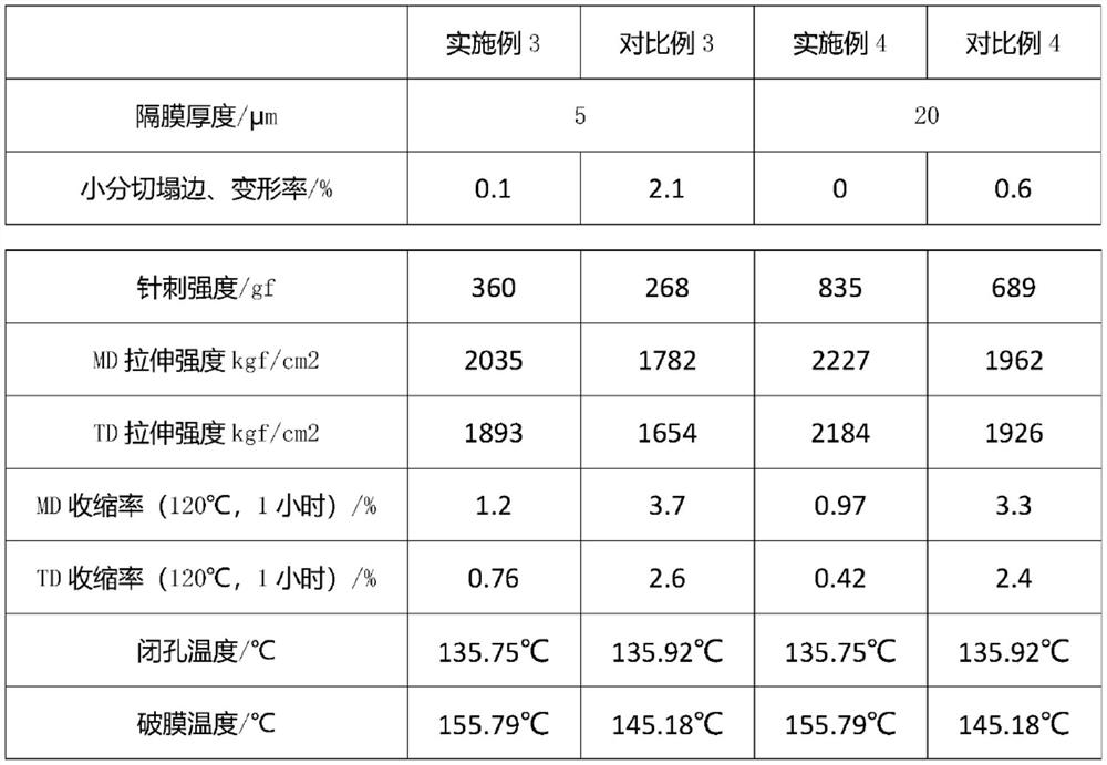
[0051]Example 3 Raw material ratio: 78 parts by weight of high molecular weight polyethylene with a viscosity average molecular weight of 1.2 million; 22 parts by weight of high molecular weight polypropylene with a viscosity average molecular weight of 1.5 million; 2.5 parts by weight of ethylene propylene copolymer with an ethylene content of 54 %, Mooney viscosity 105; 0.1 parts by weight of antioxidant is 0.06 parts by weight of antioxidant 1010 and 0.04 parts by weight of antioxidant 168 compound; performance comparison is shown in Table 3:


PUM

PropertyMeasurementUnit
thicknessaaaaaaaaaa
thicknessaaaaaaaaaa

Abstract

The invention relates to a reinforced lithium battery diaphragm and a manufacturing method thereof. The temperature difference between the closed cell temperature and the rupture temperature is 15°C to 25°C, and the percentage of small cut degradation caused by edge collapse is less than 0.3%; the thermal shrinkage rate It is less than 1.5% in the MD direction and less than 1% in the TD direction; the raw material of the reinforced lithium battery separator is a blend, and the raw materials of the blend are: 70-85 parts by weight of high molecular weight polyethylene, and 70-85 parts by weight of high molecular weight polypropylene. 15-30 parts by weight, 0.01-5 parts by weight of ethylene-propylene copolymer, and 0.01-0.3 parts by weight of antioxidant. The blend diaphragm prepared by the invention has a simple preparation process, can be produced without modifying original production equipment, and can be widely used in the field of lithium battery diaphragm manufacturing.

Description

technical field [0001] The invention relates to the technical field of diaphragm production, in particular to a reinforced lithium battery diaphragm and a manufacturing method thereof. Background technique [0002] In lithium-ion batteries, the separator is a very important part and one of the four key materials in the battery. The lithium battery separator plays the role of separating the positive and negative electrodes to prevent short circuit, and also provides a path for the conductive ions in the electrolyte. The separator The performance of the separator determines the capacity, cycle performance, safety performance and other characteristics of the battery. Therefore, the performance of the separator has an important impact on the overall performance of the battery. [0003] The current development trend of lithium batteries is higher energy density. Therefore, only a thinner separator can provide more space for the electrode material, thereby improving the energy den...

Claims


Application Information

Patent Timeline
Patent Type & Authority Patents(China)
IPC IPC(8): H01M50/414H01M50/403H01M50/494H01M10/0525H01M50/411
CPCH01M10/0525H01M50/403H01M50/411Y02E60/10
Inventor 程跃熊磊石广钦赵彪张有恒
Owner SHANGHAI ENERGY NEW MATERIALS TECH CO LTD
Why Eureka
Try Eureka