
Cast-in-place wet joint structure and bridge

A wet joint and cast-in-place technology, which is applied in bridges, bridge parts, bridge construction, etc., can solve the problems of complex structure processing, long steel welding construction time, and anchorage area affecting the appearance, so as to improve the strength and performance, hoisting Convenience in the prefabrication stage and the effect of improving the vertical shear resistance

Pending Publication Date: 2020-01-17
HUNAN UNIV
View PDF9 Cites 7 Cited by
  • Summary
  • Abstract
  • Description
  • Claims
  • Application Information

AI Technical Summary

Problems solved by technology

[0003] When ordinary concrete is used for the wet joints, in order to ensure good working performance of the wet joints, sufficient steel bars must be arranged at the wet joints, and when the number of prefabricated concrete bridge decks or prefabricated concrete beams is large, there will be The following problems: (1) The workload of steel bar welding in wet joints is huge, which increases the use of materials, labor costs and time costs; (2) The construction time of steel bar welding in wet joints is long, which has a great impact on traffic under the bridge ; (3) The on-site welding quality of the reserved steel bars is poor, and when the position deviation of the reserved steel bars on the bridge deck occurs, it is necessary to correct the position of the steel bars before welding, and the construction process is cumbersome
(4) It is inconvenient to use the vibrator when the concrete is tamped
(5) Due to the general construction of wet joints, the side parts of the beam body on both sides are used as the side formwork, and the side part of the beam body is generally a flat structure. When such a structure is used as the pouring surface, problems such as grout leakage, honeycomb, and pockmarked surface are prone to occur, which is serious Affects the structural strength of wet joints
The longitudinal connection of UHPC components can also be in the form of dry joints with prestressing and tooth keys. However, if the components are thin, the length of prestressed tendons, the setting of anchorage areas, and the appearance of the structure must be considered. , large loss of prestress, and the exposure of the anchorage area affects the appearance; on the other hand, the new and old concrete steel fibers at the joints of UHPC prefabricated components are discontinuous, which affects the tensile performance of UHPC joints. Chiseling, spraying and infiltration have limited improvement in the bonding performance of new and old UHPC materials. It is necessary to design a new joint structure through structural treatment according to its stress conditions to ensure its safety and reliability.

Method used


Image

  • Cast-in-place wet joint structure and bridge
  • Cast-in-place wet joint structure and bridge
  • Cast-in-place wet joint structure and bridge

Examples


Embodiment Construction

[0058] The specific implementation manners of the embodiments of the present invention will be described in detail below in conjunction with the accompanying drawings. It should be understood that the specific implementation manners described here are only used to illustrate and explain the embodiments of the present invention, and are not intended to limit the embodiments of the present invention.

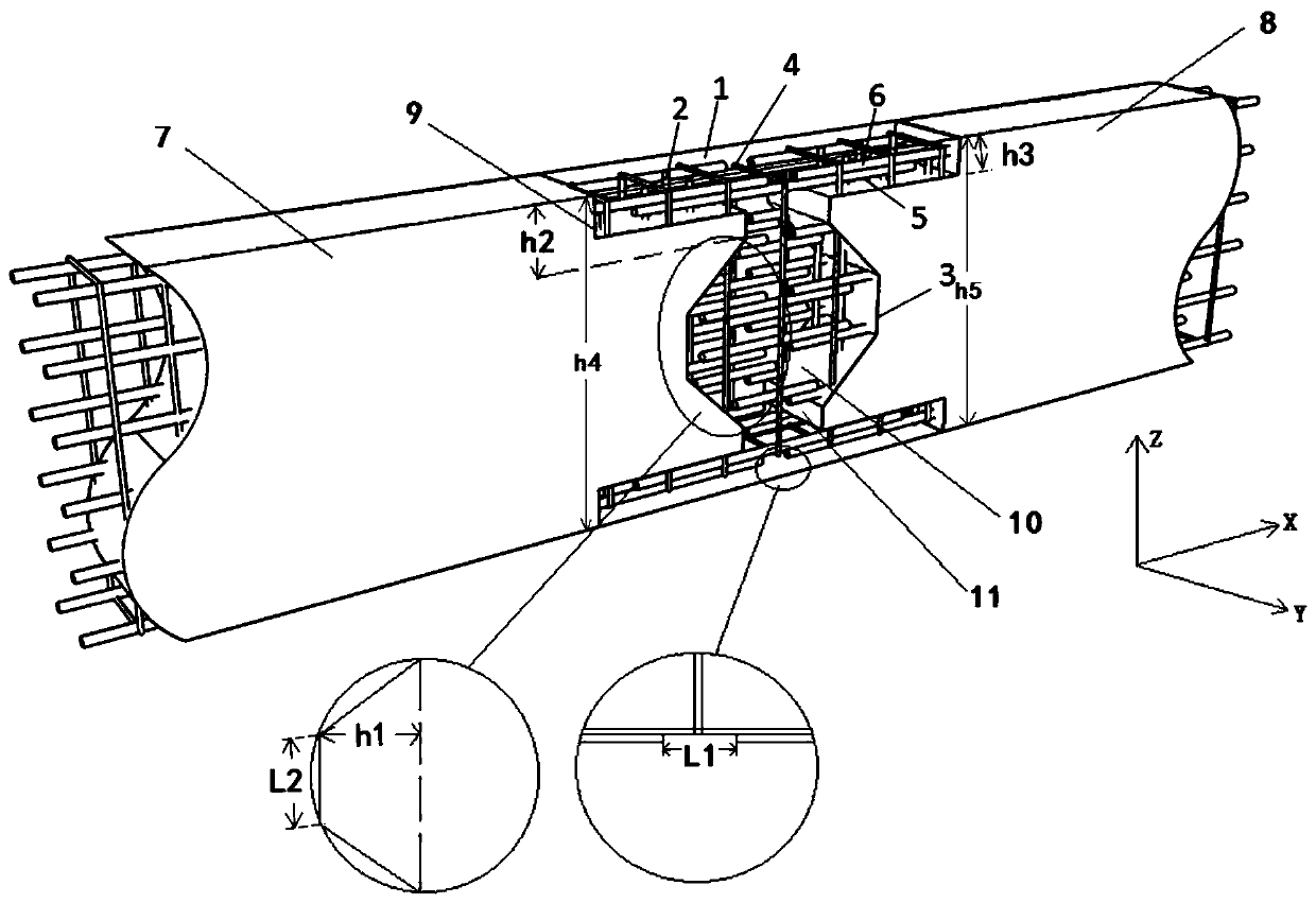
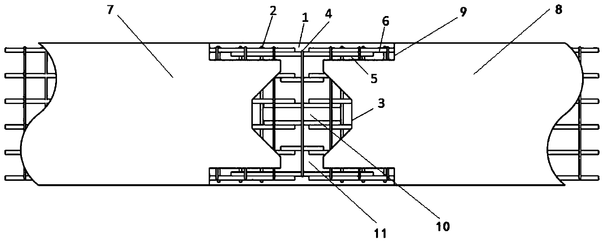
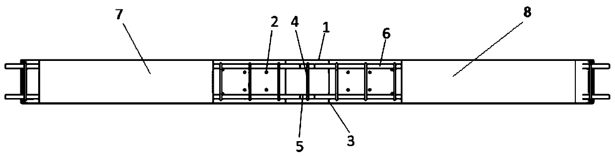
[0059] see figure 1 , figure 2 and image 3 As shown, the cast-in-place wet joint structure of the present invention includes a first UHPC prefabricated beam body 7 and a second UHPC prefabricated beam body 8, and the ends of the first UHPC prefabricated beam body 7 and the second UHPC prefabricated beam body 8 are opposite and mutually Arranged at intervals, the opposite ends of the first UHPC prefabricated beam body 7 and the second UHPC prefabricated beam body 8 are provided with notches 9 at the upper and lower parts of the height direction Z, and the first UHPC prefabricat...


PUM


Abstract

The invention relates to a bridge construction structure. The invention discloses a cast-in-place wet joint structure and a bridge. The structure comprises a first UHPC prefabricated beam body and a second UHPC prefabricated beam body, notches are formed in the upper parts and the lower parts of the opposite end parts of the first UHPC prefabricated beam body and the second UHPC prefabricated beambody in the height direction; trapezoidal notches are respectively formed in the middle parts of the opposite end parts of the first UHPC prefabricated beam body and the second UHPC prefabricated beam body in the height direction; thus, spaced rectangular spaces are formed between the opposite notches of the first UHPC prefabricated beam body and the second UHPC prefabricated beam body, the opposite notches and the rectangular spaces form T-shaped strips, and the trapezoidal notches of the first UHPC prefabricated beam body and the second UHPC prefabricated beam body are spliced to form a UHPC pouring space; embedded steel bars are arranged in the notches and the UHPC pouring space; longitudinal steel bars are arranged in the first UHPC prefabricated beam body and the second UHPC prefabricated beam body in the length direction. And UHPC blocks are poured in the T-shaped strip and the UHPC pouring space. According to the invention, wet joint shrinkage can be effectively retarded, and crack generation is reduced.

Description

technical field [0001] The invention relates to a bridge construction structure, in particular to a cast-in-place wet joint structure. In addition, the invention also relates to a bridge. Background technique [0002] With the development of modern construction technology, the performance requirements for wet joints are getting higher and higher. How to use the superiority of materials and improve the structure of wet joints to improve the performance of wet joints has also become an important content. As the main structural part of the highway bridge deck system, the wet joint structure bears heavy traffic loads on the bridge deck. The service life of the wet joint concrete has a great impact on the normal operation of the bridge. Judging from the current status of the bridges that have been put into operation, Cracking at the wet joint structure has become a common phenomenon. Most of the wet joint structures of bridges are working with joints. Even after the wet joint co...

Claims


Application Information

Patent Timeline
IPC IPC(8): E01D19/06E01D19/00
CPCE01D19/00E01D19/067
Inventor 晏班夫邵旭东王凯程怀亮刘游山
Owner HUNAN UNIV
Learn More