Eureka AIR delivers breakthrough ideas for toughest innovation challenges, trusted by R&D personnel around the world.

Full-working condition performance prediction method for compressor

A technology of performance prediction and prediction method, applied in the direction of engine function, mechanical equipment, machine/engine, etc., can solve the problems of large workload of coefficient calibration, poor prediction accuracy and poor versatility

Active Publication Date: 2020-01-17
TIANJIN UNIV
View PDF6 Cites 6 Cited by
  • Summary
  • Abstract
  • Description
  • Claims
  • Application Information

AI Technical Summary

Problems solved by technology

[0003] The traditional flow prediction method uses the blocking theoretical model and the stall theoretical model to predict the blocking flow and surge flow respectively. The theoretical model has been greatly simplified in the derivation process, and it is essentially a one-dimensional prediction model, so the prediction accuracy is poor.
Especially for compact high-speed turbocharger compressors, the prediction results are not robust
[0004] The traditional efficiency prediction method and the total pressure ratio prediction method establish a semi-empirical loss model through theoretical analysis, and the reliability depends on the specific compressor used to establish the loss model. Therefore, there are many loss models, and the coefficient calibration workload is huge, and the versatility is relatively low. Difference

Method used


Image

  • Full-working condition performance prediction method for compressor
  • Full-working condition performance prediction method for compressor
  • Full-working condition performance prediction method for compressor

Examples


Embodiment

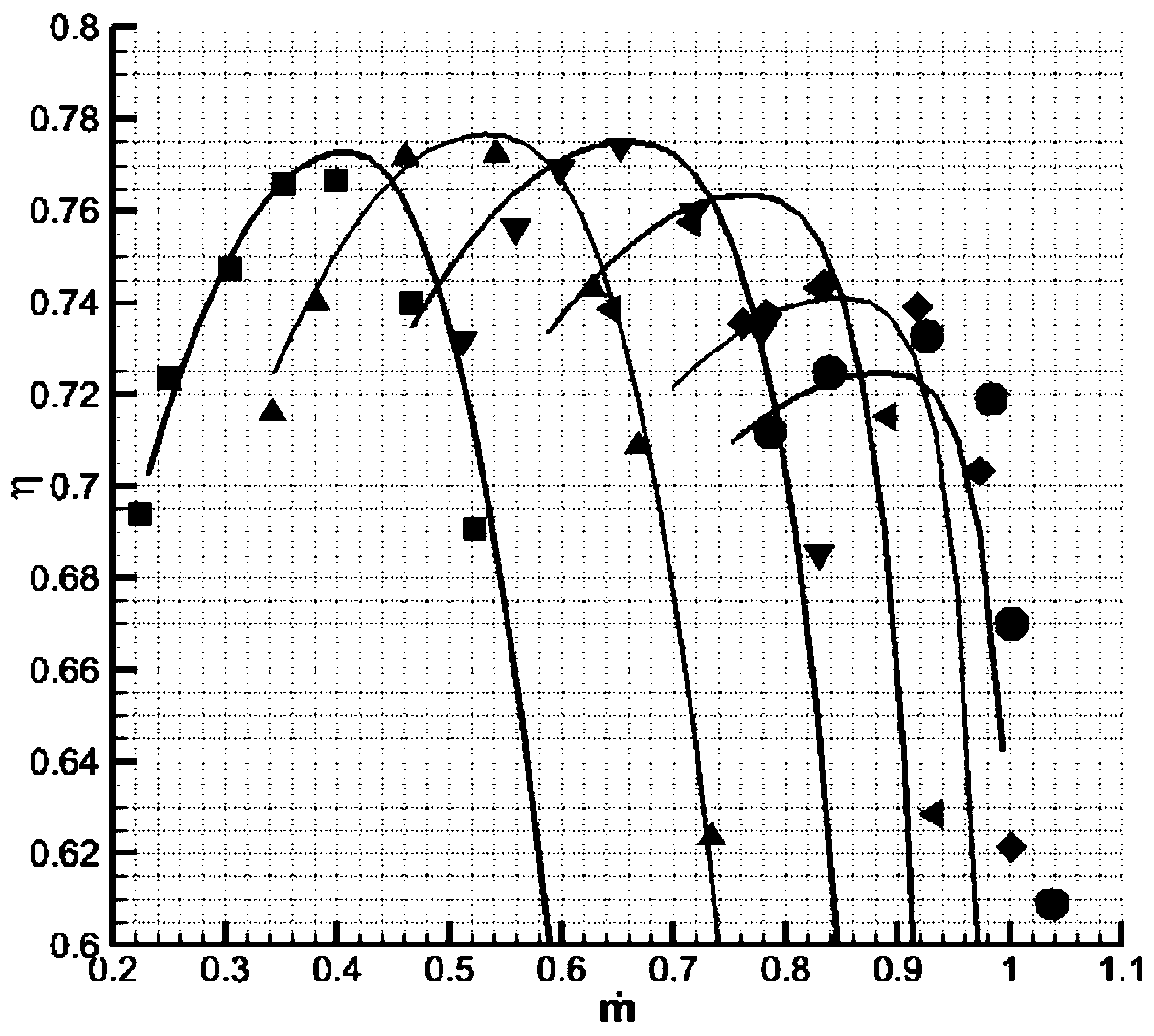
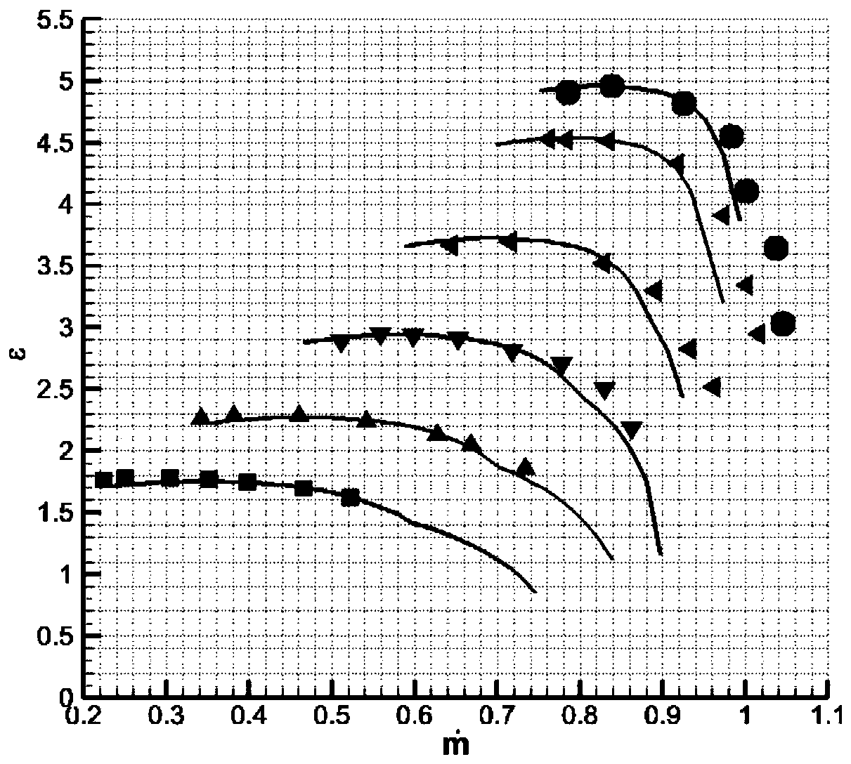
[0128] Embodiment: The full working condition aerodynamic performance prediction process of a certain turbocharger compressor from Tianjin North Engine Research Institute is as follows:

[0129] (1) Given the total inlet temperature of the compressor T t1 =298k, total inlet pressure p t1 =100000pa, specific heat ratio γ=1.4, gas constant R=287J / (kg·k). Given the geometric parameters of the compressor impeller, including: blade outlet installation angle β 2A =15deg, the number of blades Z=18, the meridional inclination of the impeller outlet θ 2 =85deg, blade outlet thickness t 2 =0.0007m, impeller outlet diameter D 2 =0.118m, the rate of change in the installation angle of the impeller outlet blade ξ=11rad / m.

[0130] (2) The parameters of a given design point, including: design machine Mach number M u2,d =1.2321, the highest design speed efficiency η p,d =0.7740, the mass flow rate at the highest efficiency point of design speed The total pressure ratio ε at the high...


PUM


Abstract

The invention discloses a full-working condition performance prediction method for a compressor, and aims at providing a rapid and accurate full-working condition aerodynamic performance prediction method so as to increase the design and optimization efficiency of the compressor. In the method, a formula is established by taking parameters of a design point as the reference to predict the flow, the efficiency and the overall pressure ratio of an off-design working condition; in a flow prediction method, firstly, the flow of the design point is converted according to an empirical formula to flow corresponding to a peak efficiency point at different rotating speeds, and then, blocking flow and surging flow at respective rotating speeds are calculated; in an efficiency prediction method, firstly, the efficiency of the design point is converted according to the empirical formula to peak efficiency at different rotating speeds, and then, the efficiency at different rotating speeds is calculated according to an elliptic piecewise approximation method; and in a prediction method for the overall pressure ratio, work factors at different rotating speeds and different flow are calculated according to the thought of the equivalent width of an impeller exit, and the work factors are combined with current efficiency to obtain the overall pressure ratio. By applying the full-working condition performance prediction method to design and optimization of the compressor, the design cycle can be remarkably shortened, and the design cost is reduced.

Description

technical field [0001] The invention relates to the field of mechanical technology, and more specifically, relates to a method for predicting the aerodynamic performance of a centrifugal compressor under all operating conditions. Background technique [0002] Centrifugal compressors are widely used in aero-engines, ground gas turbines, automobile and ship turbochargers, petrochemical compressors, and play an irreplaceable role in the fields of national defense and civil industry. In the process of aerodynamic design and optimization of a centrifugal compressor, it is usually necessary to repeatedly modify the geometric model and evaluate its aerodynamic performance under all operating conditions. Quickly and accurately predicting the aerodynamic performance of the compressor under all working conditions is a key technology in the optimization design. The traditional method generally adopts the numerical simulation method to calculate the aerodynamic performance of the whole...

Claims


Application Information

Patent Timeline
IPC IPC(8): F04D27/00
CPCF04D27/001F05D2260/82
Inventor 李孝检赵祎佳刘正先
Owner TIANJIN UNIV
Why Eureka
Eureka Blog
Learn More