A unipolar one-dimensional, two-dimensional capacitive yaw angle sensor
An angle sensor and capacitive technology, which is applied in the field of sensor measurement, can solve the problems of high installation position accuracy requirements of unipolar capacitive micro-displacement sensors, the inability to change the length of connecting cables, and complex signal conditioning circuits. The effect of small structure size and simplified signal conditioning circuit
- Summary
- Abstract
- Description
- Claims
- Application Information
AI Technical Summary
Problems solved by technology
Method used
Image
Examples
Embodiment 1
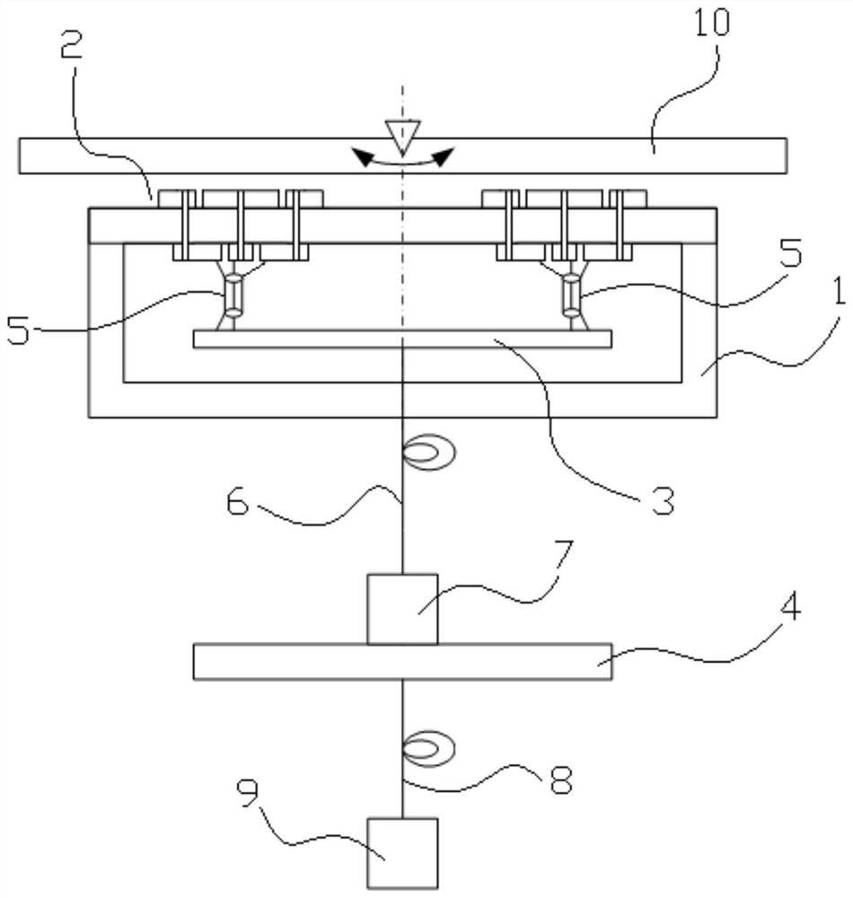
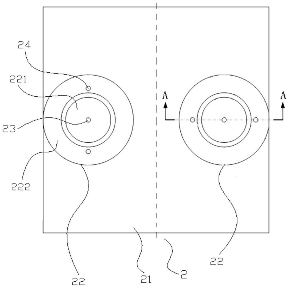
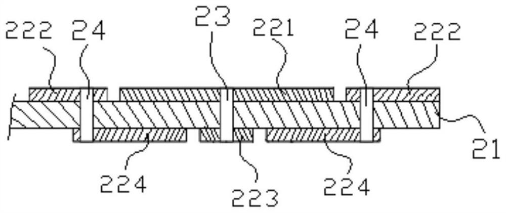
[0052] Embodiment 1: as Figure 1 to Figure 5 The unipolar 1D capacitive yaw angle sensor shown includes the sensor probe and signal conditioning circuitry.
[0053] The sensor probe includes a probe housing 1 and an induction plate 2 installed at one end of the probe housing 1. The induction plate 2 is made by PCB technology, and includes a base 21 and two groups of electrodes arranged on the base 21 and symmetrical about the deflection axis. Sensing arrays, there is a set distance L between the centers of two groups of sensing arrays, each group of sensing arrays is composed of a sensing unit 22, and each sensing unit 22 includes sensing electrodes 221 on the front side of the substrate 21, equipotential The electrode 222 and the induction connection electrode 223 and the equipotential connection electrode 224 located on the back side of the substrate 21, the equipotential electrode 222 coaxially surrounds the induction electrode 221, and an insulating ring (i.e., an annular...
Embodiment 2
[0064] Embodiment 2: as Figure 6 to Figure 9 Most of the principles and structures of the unipolar one-dimensional capacitive yaw angle sensor shown are the same as those in Embodiment 1, except that:
[0065] Each sensing array is composed of two sensing units 22 , the sensing electrodes 221 are rectangular, the equipotential electrodes 222 are rectangular rings, the sensing connection electrodes 223 are rectangular, and the equipotential connection electrodes 224 are rectangular rings.
[0066] The induction connection electrodes 223 in the two sensing units 22 of a group of sensing arrays are connected with the input end of the voltage follower X1 in a carrier modulation circuit through the central conductor of the coaxial cable (can realize induction on the two sensing electrodes 221 The output of the capacitive sensing signal), the equipotential connection electrodes 224 in the two sensing units 22 of the group sensing array are connected to the output end of the voltage...
Embodiment 3
[0075] Embodiment 3: as Figure 10 to Figure 12 , Figure 15 , Figure 16 The unipolar two-dimensional capacitive yaw angle sensor shown includes the sensor probe and signal conditioning circuitry.
[0076] The sensor probe includes a probe housing 1 and an induction plate 2 installed at one end of the probe housing 1. The induction plate 2 is made by PCB technology, and includes a base 21, which is arranged on the base 21 and is symmetrical about the X-direction deflection axis. The two first sensing units 25 and the two second sensing units 26 are arranged on the base 21 and are symmetrical about the yaw axis in the Y direction. The structure of the first sensing unit 25 is the same as that of the second sensing unit 26. Both the first sensing unit 25 and the second sensing unit 26 include an induction electrode 221 positioned on the front side of the substrate 21, an equipotential electrode 222 and an electrode positioned on the substrate. The induction connection electr...
PUM
 Abstract
Description
Claims
Application Information
 - R&D
- Intellectual Property
- Life Sciences
- Materials
- Tech Scout
- Unparalleled Data Quality
- Higher Quality Content
- 60% Fewer Hallucinations
Browse by: Latest US Patents, China's latest patents, Technical Efficacy Thesaurus, Application Domain, Technology Topic, Popular Technical Reports.
© 2025 PatSnap. All rights reserved.Legal|Privacy policy|Modern Slavery Act Transparency Statement|Sitemap|About US| Contact US: help@patsnap.com


