Supercharge Your Innovation With Domain-Expert AI Agents!

Optical fiber sensor based on optical time domain reflection technology and application method thereof

An optical fiber sensor and optical time domain reflection technology, which is applied in the field of optical fiber sensor based on optical time domain reflection technology, can solve the problems of poor anti-interference ability, difficult installation, and inability to repeatedly monitor crack changes, so as to achieve enhanced life, increased sensitivity, The effect of good applicability

Pending Publication Date: 2020-01-17
TIANJIN UNIV
View PDF0 Cites 2 Cited by
  • Summary
  • Abstract
  • Description
  • Claims
  • Application Information

AI Technical Summary

Problems solved by technology

This optical fiber sensor is simple to manufacture, stable in performance and strong in operability, which solves the problems of difficult installation, poor anti-interference ability and inability to repeatedly monitor crack changes in the existing optical fiber sensor in the process of structural monitoring

Method used


Image

  • Optical fiber sensor based on optical time domain reflection technology and application method thereof
  • Optical fiber sensor based on optical time domain reflection technology and application method thereof
  • Optical fiber sensor based on optical time domain reflection technology and application method thereof

Examples


Embodiment Construction

[0027] The present invention will be described in further detail below in conjunction with the accompanying drawings and specific embodiments. It should be understood that the specific embodiments described here are only used to explain the present invention, not to limit the present invention.

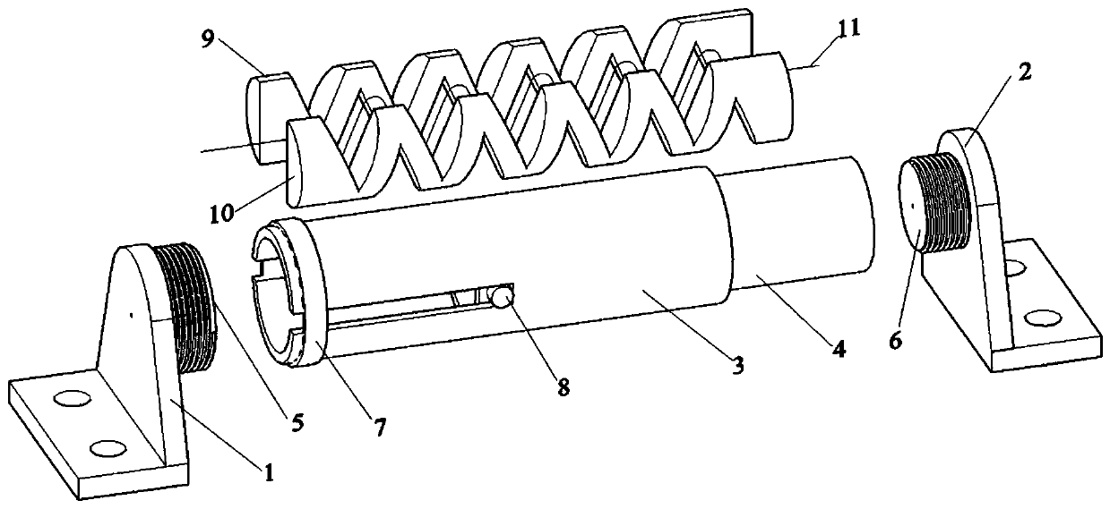
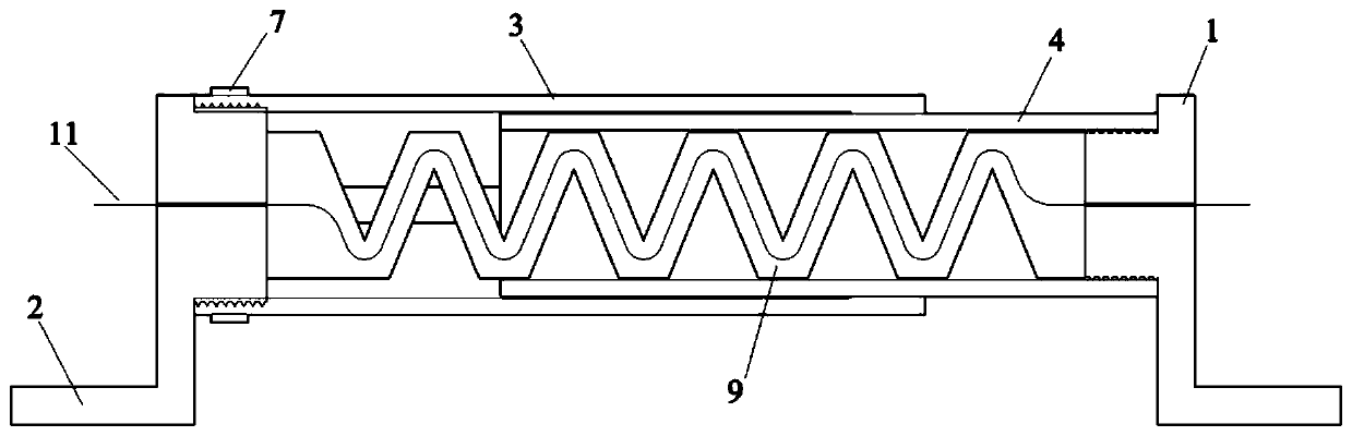
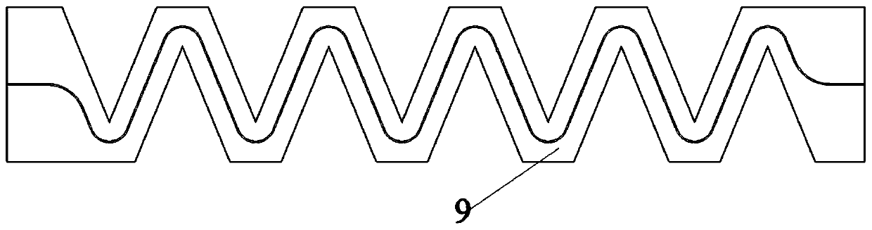
[0028] A fiber optic sensor based on optical time domain reflectometry, such as figure 1 , 2 As shown, it includes an outer cylindrical protective shell 3, an inner cylindrical protective shell 4, a first fixed gusset 1 and a second fixed gusset 2 with optical fiber outlets at the left and right ends, and is arranged in the inner cylindrical protective shell 4 at the same time There are a first linear stretcher 9 and a second zigzag stretcher 10, and bare optical fibers 11 are arranged in the first and second zigzag stretchers; the second zigzag stretcher 10 is glued to the first zigzag On the linear expander 9; at the same time, one end of the outer cylindrical protective shell 3 i...


PUM

PropertyMeasurementUnit
Diameteraaaaaaaaaa
Bending angleaaaaaaaaaa
Lengthaaaaaaaaaa

Abstract

The invention discloses an optical fiber sensor based on an optical time domain reflection technology and an application method thereof. The sensor comprises an inner cylindrical protective shell, anouter cylindrical protective shell, a first fixing angle brace and a second fixing angle brace that are provided with an optical fiber outlets at a left end and a right end, and a crease-line retractor. A bare fiber is configured as a section arranged inside the crease-line retractor in a folding shape identical to the crease-line retractor, with leading portions at both ends being 10mm in bendingdiameter and a middle bending portion being 5mm in bending diameter. During use, connecting bolts of the first and the second fixing angle braces are rotated firstly until the internal crease-line retractor is compressed, then the inner cylindrical protective shell is pushed to compress the crease-line retractor by 20-25mm, ensuring to monitor expansion and closure of structural cracks, afterwards the crease-line retractor is firmly secured to both sides of the structural cracks. The optical fiber sensor of the present invention is simple to manufacture and low in cost, suitable for monitoring change process of the structural cracks for a long time, highly operatable, and capable of being directly arranged on surface of a structure, simplifying complicated monitoring process.

Description

technical field [0001] The invention belongs to the technical field of optical fiber sensor monitoring, and in particular relates to an optical fiber sensor based on optical time domain reflection technology and a use method thereof. Background technique [0002] Optical time domain reflectometry is a technology that obtains optical power attenuation by measuring the Rayleigh scattering and Fresnel reflection power of optical pulses when they are transmitted in an optical fiber. The optical fiber monitors the cracks of the concrete structure by embedding optical fibers on the surface or inside of the concrete. When the structural state of the concrete changes, the bending and deformation of the optical fiber will cause the conduction mode field in the optical fiber to change, and Rayleigh scattering and Fresnel will occur. The optical time domain reflectometer can monitor the loss change of the optical power at this time. The bending shape of the optical fiber, that is, the...

Claims


Application Information

Patent Timeline
IPC IPC(8): G01B11/14G01D5/353
CPCG01B11/14G01D5/35361G01D5/35358
Inventor 王仁超马钰明王彦磊陈宏运
Owner TIANJIN UNIV
Features
  • R&D
  • Intellectual Property
  • Life Sciences
  • Materials
  • Tech Scout
  • Unparalleled Data Quality
  • Higher Quality Content
  • 60% Fewer Hallucinations
Learn More