
Indoor Internet of Things multi-target wireless charging system and positioning and charging method thereof

A wireless charging, multi-objective technology, applied in the direction of electrical components, circuit devices, etc., can solve the problems of restricting the development of indoor wireless charging technology, the long-term energy supply bottleneck of IoT nodes, and restricting the development and application of IoT, and achieve various charging methods , Eliminate charging dead angle, high degree of automation effect

Active Publication Date: 2020-01-17
NANJING INST OF TECH
View PDF6 Cites 1 Cited by
  • Summary
  • Abstract
  • Description
  • Claims
  • Application Information

AI Technical Summary

Problems solved by technology

Long-term energy supply of IoT nodes has been a bottleneck due to lack of means to recharge batteries
However, this technology also has the following problems: first, the light propagates in a straight line, how to accurately align the laser with the photocell, especially how to achieve charging during the movement of the node to be tested; The dead zone problem; Third, how to realize simultaneous charging of multiple charging nodes
These problems severely limit the development of indoor wireless charging technology, and also limit the application and development of the Internet of Things
Therefore, the indoor wireless power supply technology of nodes severely limits the development and application of the Internet of Things

Method used


Image

  • Indoor Internet of Things multi-target wireless charging system and positioning and charging method thereof
  • Indoor Internet of Things multi-target wireless charging system and positioning and charging method thereof
  • Indoor Internet of Things multi-target wireless charging system and positioning and charging method thereof

Examples


Embodiment Construction

[0040] The present invention will be further described below in conjunction with the accompanying drawings.

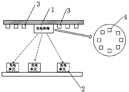
[0041] like figure 1 As shown, an indoor wireless charging device of the present invention includes a charging terminal 1 and several charging units 2, the charging terminal 1 is generally placed in the center of the ceiling, other charging edge modules 3 are placed around the ceiling, and the charging units 2 are placed indoors On the lower plane, the charging terminal 1, each charging edge module 3 and each charging unit 2 are connected in communication, and the charging terminal 1 and the charging edge module 3 are used to locate and charge the charging unit 2 to be charged.

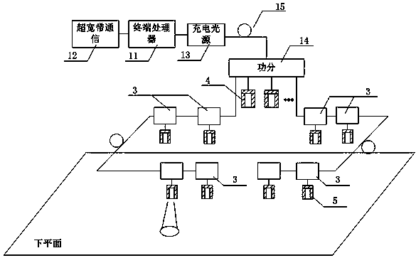
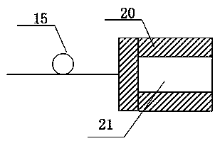
[0042] like Figures 1 to 5As shown, the charging terminal 1 includes a terminal charging probe 4, a terminal processor 11, an ultra-wideband communication module 12, a charging light source 13, a power divider 14, and an optical fiber 15; The signal port of the broadband communication modul...


PUM


Abstract

The invention discloses an indoor Internet of Things multi-target wireless charging system and a positioning and charging method thereof, the system comprises a charging unit, a charging terminal anda plurality of charging edge modules, and the charging edge modules are distributed by taking the charging terminal as the center; the charging terminal, the charging edge modules and the charging units are in communication connection, the charging terminal comprises a terminal charging probe, a terminal processor, an ultra-wideband communication module, a charging light source, a power divider and an optical fiber, and each charging edge module comprises an edge charging probe, a charging edge processor, an ultra-wideband communication module, an optical switch, an optical fiber and the like.According to the invention, the optical fiber light path is designed and the edge charging module is arranged around the charging terminal; the problems of difficulty in node charging, dead zone of infrared charging and the like of the existing Internet of Things are solved, the functions of multi-target zero-dead-angle wireless charging, mobile charging unit charging, quick charging, multi-anglecharging and the like can be realized, the charging modes are diversified, the charging continuity is good, the positioning speed is high, and the precision is high.

Description

technical field [0001] The invention relates to the field of indoor wireless charging, in particular to an indoor Internet of Things multi-target wireless charging system and a positioning and charging method thereof. Background technique [0002] With the continuous maturity and development of the Internet of Things technology, a large number of sensors and control nodes are built into a network through wireless technology, which plays an extremely important role in the monitoring and management of the system. Long-term energy supply for IoT nodes has been a bottleneck due to lack of means to recharge batteries. The existing solution is to reduce the power consumption of the node as much as possible and prolong the working life of the battery. However, this scheme imposes severe restrictions on the performance and functions of nodes, such as requiring nodes to be in a sleep state for a long time, and only work and communicate for a short time. Although this method effecti...

Claims


Application Information

Patent Timeline
Patent Type & Authority Applications(China)
IPC IPC(8): H02J50/30H02J50/90H02J50/40H02J50/80
CPCH02J50/30H02J50/90H02J50/40H02J50/80
Inventor 韦朴邓路李辉
Owner NANJING INST OF TECH
Learn More