
Wave energy heat storage type seawater temperature difference power generation device

A thermoelectric power generation and regenerative technology, applied in ocean energy power generation, steam engine installations, engine components, etc., can solve the problems of unstable mechanical energy and electric energy signals, low wave energy utilization efficiency, limited net power generation, etc., and achieve stable growth. Safety and security, protection security, energy saving effect

Pending Publication Date: 2020-01-21
DALIAN UNIV OF TECH
View PDF0 Cites 1 Cited by
  • Summary
  • Abstract
  • Description
  • Claims
  • Application Information

AI Technical Summary

Problems solved by technology

Due to the randomness of waves in actual sea conditions, the converted mechanical energy and electrical energy signals are unstable, and additional rectification devices need to be designed, resulting in low wave energy utilization efficiency and high construction costs.
[0004] The ocean temperature difference energy technology mainly uses the temperature difference between the surface heat source seawater and the deep cold source seawater to generate electricity. The power generation process is relatively stable, but additional pumps are needed to extract the heat source seawater and cold source seawater. Therefore, the device itself consumes a lot of energy, and the net power generation limited quantity, poor efficiency

Method used


Image

  • Wave energy heat storage type seawater temperature difference power generation device
  • Wave energy heat storage type seawater temperature difference power generation device
  • Wave energy heat storage type seawater temperature difference power generation device

Examples


Embodiment Construction

[0032] Below in conjunction with accompanying drawing and specific embodiment the present invention is described in further detail:

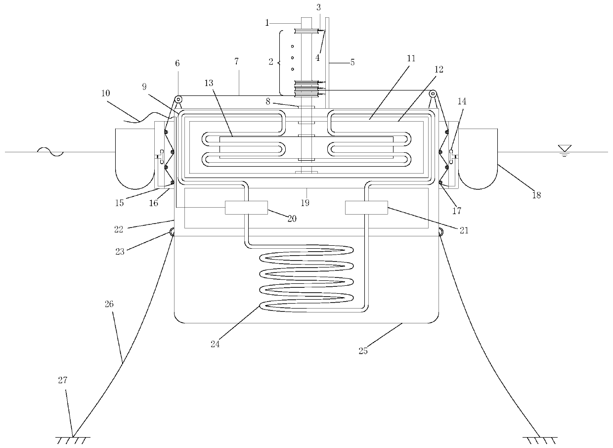
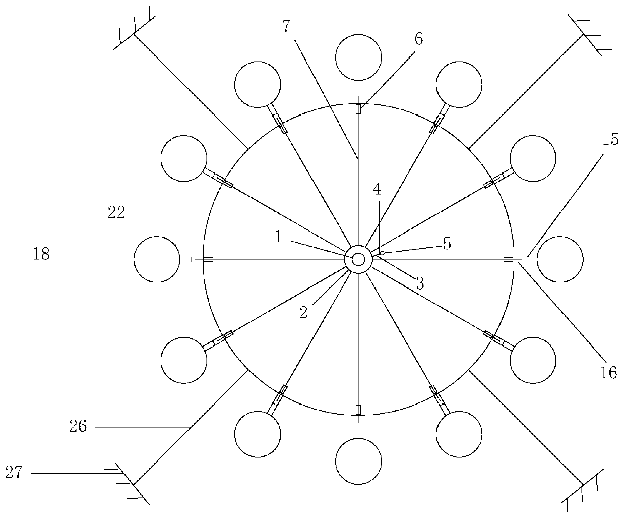
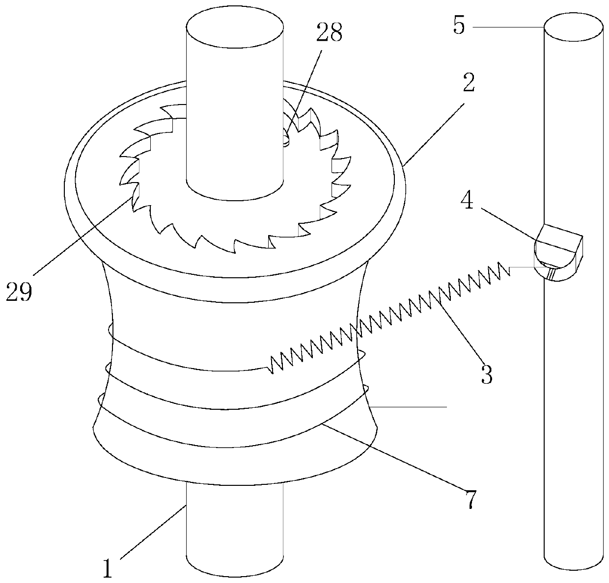
[0033] The wave energy thermal storage type seawater temperature difference power generation device mainly includes a floater energy harvesting system, a platform system and an anchoring system. The buoy energy harvesting system mainly includes a buoy 18 , a guide rail layer 15 , a pulley layer 16 , a guide rail pulley 14 , a direction changing pulley 17 , a platform pulley 6 and a wire rope 7 . The platform system mainly includes a thermal liquid tank 12, a power generation cabin 19 and a cooling layer. The hot liquid tank 12 includes a flywheel shaft 1, a rotating sleeve 2, a preload spring 3, a buckle 4, a fixed column 5, a bearing 8, a heat collecting pipe 9, a heat insulation layer 11, a flywheel 13, a pawl 28 and an inner ratchet 29 . The generating chamber 19 includes cables 10 , a turbine generator 20 and a working medium pump 21 . Th...


PUM


Abstract

The invention belongs to the technical field of ocean energy utilization, and provides a wave energy heat storage type seawater temperature difference power generation device. The wave energy heat storage type seawater temperature difference power generation device comprises a floater energy obtaining system, a platform system and an anchoring system. A whole set of friction liquid is used for heating and heat storage, a power generation device is arranged in a platform, and thus the adaptive capacity of the whole system to the external environment is improved. The manner of friction heating of a flywheel and liquid is adopted, and heat generation is efficient. An inner ratchet wheel and pawl device is used for controlling movement of the flywheel, the flywheel rotates in one direction allthe time, when the rotating speed of the flywheel exceeds the rotating speed of the inner ratchet wheel, external wave energy cannot be transmitted to the flywheel through movement of the inner ratchet wheel, and therefore the rotating speed upper limit of the flywheel is limited, and the safety of a flywheel system is protected. A heat collection pipeline makes direct contact with hot liquid, and heat transmission is efficient. A water permeable net protects the safety of a heat dissipation pipeline, and cold seawater can freely circulate around the heat dissipation pipeline. Compared with atraditional ocean temperature difference power generation device, energy consumed for extracting deep cold seawater is saved.

Description

technical field [0001] The invention belongs to the technical field of ocean energy utilization, in particular to an ocean wave energy and ocean temperature difference energy generating device. Background technique [0002] The world's energy demand is increasing day by day, and fossil energy is gradually being exhausted. The full development of renewable energy will help mankind break through the current energy crisis. Among all kinds of renewable energy forms, ocean energy reserves are huge, widely distributed, and have great potential for development. The wave energy with a reserve capacity of 2.5 billion kW and the temperature difference energy with a capacity of 2 billion kW are the two most important forms of ocean energy. [0003] Existing wave energy utilization technologies (such as oscillating buoy type, raft type, nodding duck type, oscillating water column type, etc.) usually need to go through multi-stage energy conversion, first convert wave energy into mechan...

Claims


Application Information

Patent Timeline
IPC IPC(8): F03G7/05F03B13/16F01K27/00F01D15/10
CPCF01D15/10F01K27/00F03B13/16F03G7/05Y02E10/30
Inventor 张崇伟庄乾泽宁德志
Owner DALIAN UNIV OF TECH
Learn More