Electroplating device for plastic automobile ornaments

A technology for electroplating equipment and automobiles, applied in plating baths, electrolytic processes, electrolytic components, etc., can solve problems such as unfavorable use, inability to use electrolyte, and unfavorable environmental users, to ensure operating efficiency, improve tightness, and recover costs. Effect

Inactive Publication Date: 2020-01-24
阮松益
View PDF1 Cites 9 Cited by
  • Summary
  • Abstract
  • Description
  • Claims
  • Application Information

AI Technical Summary

Problems solved by technology

The performance of the coating is different from that of the base metal, and has new features, and the electroplating equipment is the equipment to realize the electroplating technology; the existing plastic shell electroplating equipment has certain disadvantages when used. First, the electrolyte cannot be moved, resulting in insufficient electrolyte. Electrolysis has certain adverse effects. Secondly, it cannot reduce the noise generated by the operation of the motor, which is not good for the environment and users. In addition, when the existing electroplating equipment is in use, it cannot reduce t

Method used


Image

  • Electroplating device for plastic automobile ornaments
  • Electroplating device for plastic automobile ornaments
  • Electroplating device for plastic automobile ornaments

Examples


Embodiment 1

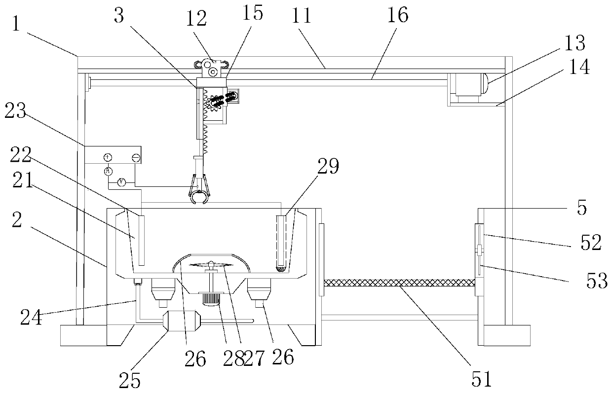
[0033] see figure 1 , an electroplating equipment for plastic automotive accessories, comprising a frame 1, the bottom of the frame 1 is respectively provided with an electroplating box 2 and a storage cavity 5, the electroplating box 2 is used for electroplating treatment, and the storage cavity 5 is used for electroplating. Temporary artifacts. The frame 1 is movably equipped with a lifting frame 3, and the lifting frame 3 is used for clamping workpieces. The electroplating box 2 is provided with an electroplating pool 21, the electroplating pool 21 has a built-in electroplating solution, the bottom of the electroplating pool 21 is externally connected with an infusion conduit 24, and a booster pump 25 is installed on the infusion conduit 24, and the frame 1 A power supply 23 is installed on the side of the power supply 23, and the positive electrodes of the power supply 23 are respectively connected to metal parts 22 (anodes) through several electrical connection lines. T...

Embodiment 2

[0045] see figure 1 , this embodiment serves as a further optimization of the first embodiment, on the basis of which, the storage chamber 5 is built with a loading net plate 51, and the bottom of the loading net plate 51 is provided with a liquid contact chamber. A blowing cavity 52 is provided on the side of the storage cavity 5, and a blower 53 is installed in the blowing cavity 52.

[0046] For the workpiece that has been electroplated, the application uses the above-mentioned lifting and horizontal displacement mechanism to place the workpiece on the loading net plate 51, and the liquid on the surface of the workpiece passes through the loading net plate 51 and flows into the liquid receiving chamber for recycling. Blowing cavity 52 is arranged on the side, further carries out air-drying to workpiece, improves its blow-drying speed.


PUM


Abstract

The invention relates to the technical field of electroplating, and particularly relates to an electroplating device for plastic automobile ornaments. The device comprises a rack, wherein the bottom of the rack is provided with an electroplating box and a storage cavity, a lifting frame is movably mounted on the rack, an electroplating pool is arranged in the electroplating box, the electroplatingpool is internally provided with electroplating liquid, the bottom of the electroplating pool is externally connected with an infusion duct, a booster pump is installed on the infusion duct, a powersupply is installed on the side edge of the rack, a positive electrode of the power supply is connected with metal pieces through a plurality of electrical connecting wires correspondingly, the metalpieces are located in the electroplating pool, a workpiece clamped on the lifting frame is connected with a negative electrode of the power supply through an electric connecting wire, the lifting frame is arranged on the rack, a lifting plate is mounted on the lifting frame, and a clamping frame is installed at the bottom end of the lifting plate. According to the device, through the transfer of metal ions, the electroplating treatment on the surface of the workpiece is completed, and the effect of three-dimensional azimuth adjustment can be achieved.

Description

technical field [0001] The invention relates to the technical field of electroplating, in particular to electroplating equipment for plastic automobile accessories. Background technique [0002] Electroplating refers to a surface processing method in which in a salt solution containing the metal to be plated, the base metal to be plated is used as the cathode, and through electrolysis, the cations of the metal to be plated in the plating solution are deposited on the surface of the base metal to form a coating. . The performance of the coating is different from that of the base metal, and has new features, and the electroplating equipment is the equipment to realize the electroplating technology; the existing plastic shell electroplating equipment has certain disadvantages when used. First, the electrolyte cannot be moved, resulting in insufficient electrolyte. Electrolysis has certain adverse effects. Secondly, it cannot reduce the noise generated by the operation of the m...

Claims


Application Information

Patent Timeline
IPC IPC(8): C25D5/56C25D17/02C25D17/00C25D21/02C25D21/04C25D17/06
CPCC25D5/56C25D17/00C25D17/02C25D17/06C25D21/02C25D21/04
Inventor 阮松益
Owner 阮松益
Why Eureka
Try Eureka