
Pressure relief electric explosion valve

A technology of electric explosion and valve, applied in the direction of valve details, safety valves, engine components, etc., can solve the problems of large volume and complex structure of electric explosion valve, and achieve the effect of simple structure, small volume and good economy

Pending Publication Date: 2020-01-24
SHENYANG AEROSPACE XINGUANG GRP
View PDF0 Cites 0 Cited by
  • Summary
  • Abstract
  • Description
  • Claims
  • Application Information

AI Technical Summary

Problems solved by technology

[0003] The present invention aims at the problems existing in the above-mentioned prior art, and provides a decompression type electric explosion valve, which solves the problems of large volume and complex structure of the electric explosion valve in the aerospace power system in the prior art

Method used

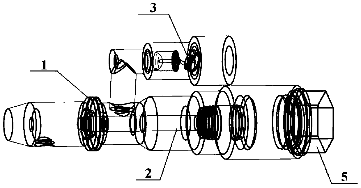
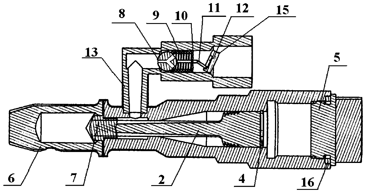
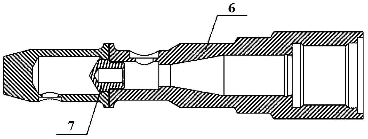

Image

  • Pressure relief electric explosion valve
  • Pressure relief electric explosion valve
  • Pressure relief electric explosion valve

Examples


Embodiment Construction

[0026] In conjunction with the accompanying drawings of the description, this invention is carefully interpreted.

[0027] Such as figure 1 , figure 2 As shown, a decompression electric explosion valve includes: a housing assembly 1 , a piston 2 , a decompression pipeline device 3 , a snap ring 4 , and an igniter 5 . The piston 2 is placed inside the housing assembly 1 and fixed with a snap ring 4 , and the decompression pipeline device 3 is installed at the outlet of the housing assembly 1 . The igniter 5 is installed at the tail end of the shell assembly 1 and sealed by the gasket 16. The igniter ignites and pushes the piston, cuts off the diaphragm, opens the electric explosion valve, and makes the fluid enter the decompression pipeline device.

[0028] Such as image 3 The shown housing assembly 1 includes: a housing 6 and a diaphragm 7 , and the diaphragm 7 is fixed at the front end of the housing 6 . The front end of the piston 2 is pressed against the diaphragm 7 ,...


PUM


Abstract

The invention provides a pressure relief electric explosion valve. The pressure relief electric explosion valve comprises a shell assembly, a piston, a snap ring, a pressure relief pipe device and anigniter. The piston is mounted in the shell assembly. The tail of the piston is fixed through the snap ring to prevent relative movement between the piston and the shell assembly. The igniter is mounted at the tail end of the shell assembly. The shell assembly comprises a shell and a diaphragm. During operation, the igniter pushes the piston to break through the diaphragm to enable fluid to get into the shell. The pressure relief pipe device comprises a steel ball, a spring, a fixed support, a connecting rod, a baffle and a pressure relief shell. When the fluid pushes the steel ball at a certain pressure, the steel ball and the baffle are in linkage to enable part of fluid passes through the steel ball and the baffle to go into an inner cavity of the pressure relief shell. The higher the flow rate of the fluid is, and the less the flow of ingoing fluid is. The output pressure is reduced, and the pressure reduction effect is achieved. When the flow rate of the fluid is slowed down, theflow of the fluid is increased, the output pressure is increased, and the pressure control effect is achieved. The pressure relief electric explosion valve is simple in structure and good in economy and has the characteristics of being small in size, light in weight and the like.

Description

technical field [0001] The invention relates to the technical field of aerospace power devices, in particular to a decompression electric explosion valve. Background technique [0002] With the development of the aerospace field, higher requirements are put forward for the aerospace power system. Today, the aerospace power system is developing towards the trend of miniaturization and light weight. However, the current aerospace power system is too large, often due to excessive volume and mass, resulting in poor performance of aerospace power devices. At the same time, there are too few combined and lightweight devices in the aerospace power system, and the device structure is complex, and the design, production and processing steps are complicated, resulting in poor manufacturing economy. Contents of the invention [0003] The present invention aims at the problems existing in the above-mentioned prior art, and provides a decompression electric explosion valve, which sol...

Claims


Application Information

Patent Timeline
IPC IPC(8): F16K13/00F16K31/00F16K17/22F16K17/32
CPCF16K13/04F16K17/22F16K17/32F16K31/00
Inventor 王维东刘博廉彬胡森苏雷宋福英赵龙胜王冲
Owner SHENYANG AEROSPACE XINGUANG GRP
Learn More