Cavity filter

A cavity filter and cavity technology, applied in the field of filters, can solve problems such as failure to meet production index requirements, weak transmission zero point, and small adjustable range, to meet the needs of use and miniaturization of filters, and improve production Efficiency, the effect of saving maintenance costs

Inactive Publication Date: 2020-01-24
SHENZHEN GRENTECH RF COMM LTD
View PDF5 Cites 4 Cited by
  • Summary
  • Abstract
  • Description
  • Claims
  • Application Information

AI Technical Summary

Problems solved by technology

[0003] Limited to the current machining process, the dimensional accuracy of the filter cannot be effectively improved. At the same time, it is also affected by various aspects such as the assembly difference of the production line production staff and the processing error of the resonance column. During the debugging process of the assembled finished product, the traditional filter The non-adjustable error of the capacitive cross-coupling rod, the transmission zero point generated by the capacitive cross-coupling rod is strong or weak, and some even cannot meet the production index requirements; at the same time, the adjustable range is relatively small, only about 8 megabytes, which is a trend in today's mobile communication equipment During the development of small, light, thin and high performance, the size of the filter is getting smaller and smaller. The adjustable range of the previous adjustable capacitor cross-coupling rod can no longer meet the requirements of the miniaturized filter.

Method used


Image

  • Cavity filter
  • Cavity filter
  • Cavity filter

Examples


Embodiment Construction

[0020] The present invention will be further described below in conjunction with the accompanying drawings and embodiments.

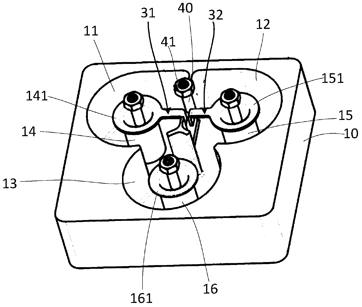
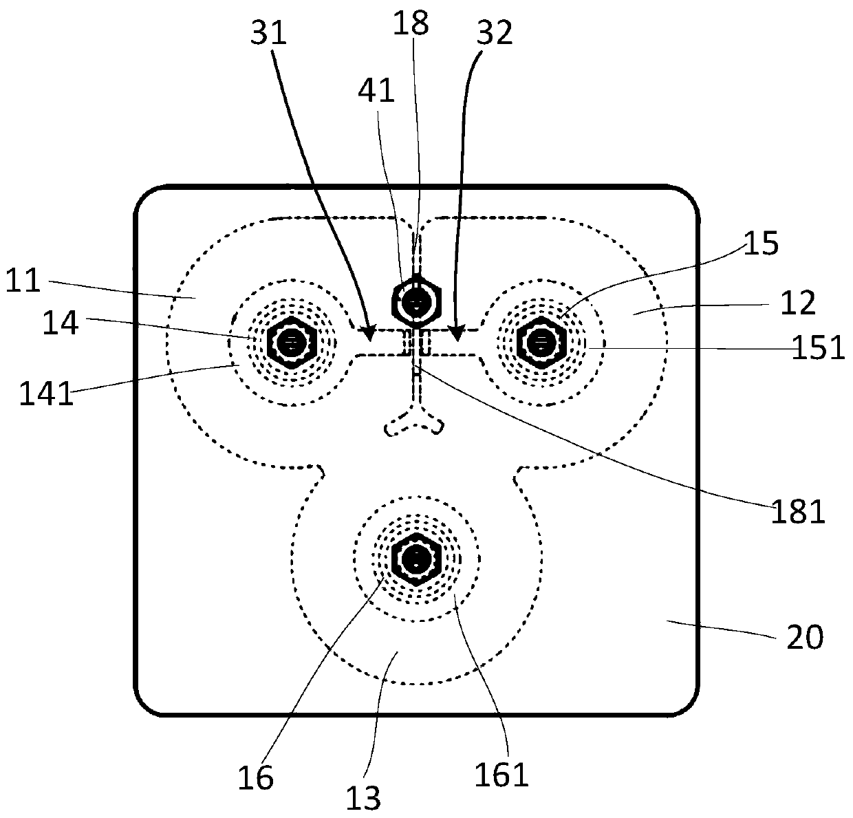
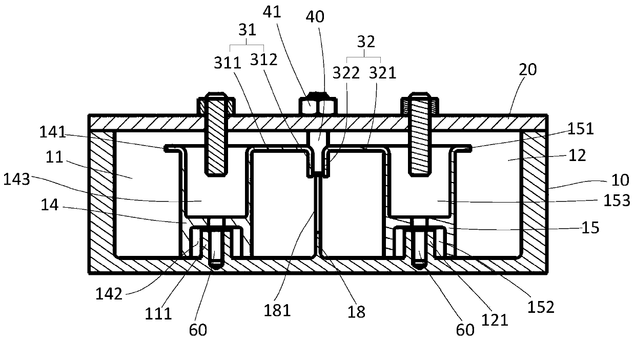
[0021] refer to Figure 1 to Figure 3 , a cavity filter provided by the present invention includes a cavity 10 with an open end, a cover plate 20 installed on the open end of the cavity 10, three resonant cavities located inside the cavity 10, a partition wall 18, and a cross-coupling structure and a commissioning coupling screw 40 mounted to the cover plate 20 . The three resonant cavities are respectively a first resonant cavity 11 , a second resonant cavity 12 and a third resonant cavity 13 . The partition wall 18 is located between the first resonant cavity 11 and the second resonant cavity 12 , thereby separating the first resonant cavity 11 and the second resonant cavity 12 . The third resonant cavity 13 communicates with the first resonant cavity 11 and the second resonant cavity 12 respectively. The first resonant cavity 11 is provided with a...


PUM


Abstract

The invention relates to a cavity filter, which comprises a cavity with one end open, a cover plate installed at the open end of the cavity, a first resonant cavity and a second resonant cavity arranged in the cavity, a partition wall positioned between the first resonant cavity and the second resonant cavity, a cross coupling structure, and a debugging coupling screw installed on the cover plate.A first coupling resonant column is arranged in the first resonant cavity. A second coupling resonant column is arranged in the second resonant cavity. The cross coupling structure comprises a firstcoupling piece formed on the first coupling resonant column and a second coupling piece formed on the second coupling resonant column. The partition wall is provided with a groove. The first couplingpiece and the second coupling piece are oppositely arranged and located on the two sides of the groove respectively, and the tail end of the first coupling piece and the tail end of the second coupling piece are close to the groove. The debugging coupling screw penetrates through the cover plate and extends into the groove. According to the invention, the strength of the transmission zero can be conveniently debugged without dismounting the cover plate, and the adjustable range is large.

Description

【Technical field】 [0001] The invention relates to the field of filters, in particular to a cavity filter. 【Background technique】 [0002] As a key component of the mobile communication system, the cavity filter is widely used in various mobile communication systems. In the development process of today's mobile communication equipment tending to be small, light, thin and high-performance, customers need to pay attention to the passive cavity The out-of-band rejection requirements of the filter are becoming more and more stringent, and the insertion loss requirements are getting smaller and smaller. Therefore, in the passive cavity filter we design, it is usually necessary to add several capacitive cross-coupling rods to generate transmission zeros to meet customer needs. . [0003] Limited to the current machining process, the dimensional accuracy of the filter cannot be effectively improved. At the same time, it is also affected by various aspects such as the assembly diffe...

Claims


Application Information

Patent Timeline
Patent Type & Authority Applications(China)
IPC IPC(8): H01P1/207H01P7/00H01P1/00
CPCH01P1/00H01P1/207H01P7/00
Inventor 赵小青林湘雄饶风顺
Owner SHENZHEN GRENTECH RF COMM LTD
Why Eureka
Try Eureka