Thin imaging lens group

A lens group and imaging technology, applied in the field of lens groups, can solve the problems of high product unit price, high manufacturing cost, and difficulty in miniaturization

Active Publication Date: 2020-01-31
NEWMAX TECH
View PDF14 Cites 3 Cited by
  • Summary
  • Abstract
  • Description
  • Claims
  • Application Information

AI Technical Summary

Problems solved by technology

However, most of the current biometric identification systems used in mobile devices use the capacitor principle. Although it can reduce the size required for the biometric identification system, the circuit structure is too complicated, which makes the manufacturing cost too high and the relative unit price of the product is also high.
[0003]At present, although there are t...

Method used


Image

  • Thin imaging lens group
  • Thin imaging lens group
  • Thin imaging lens group

Examples


no. 1 example

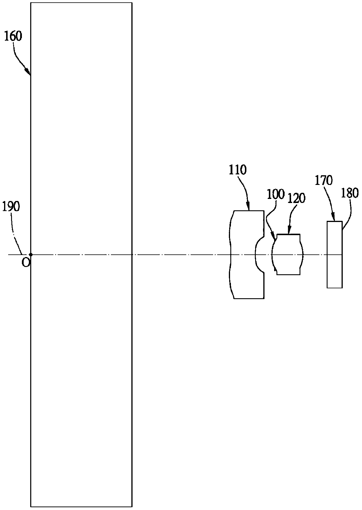
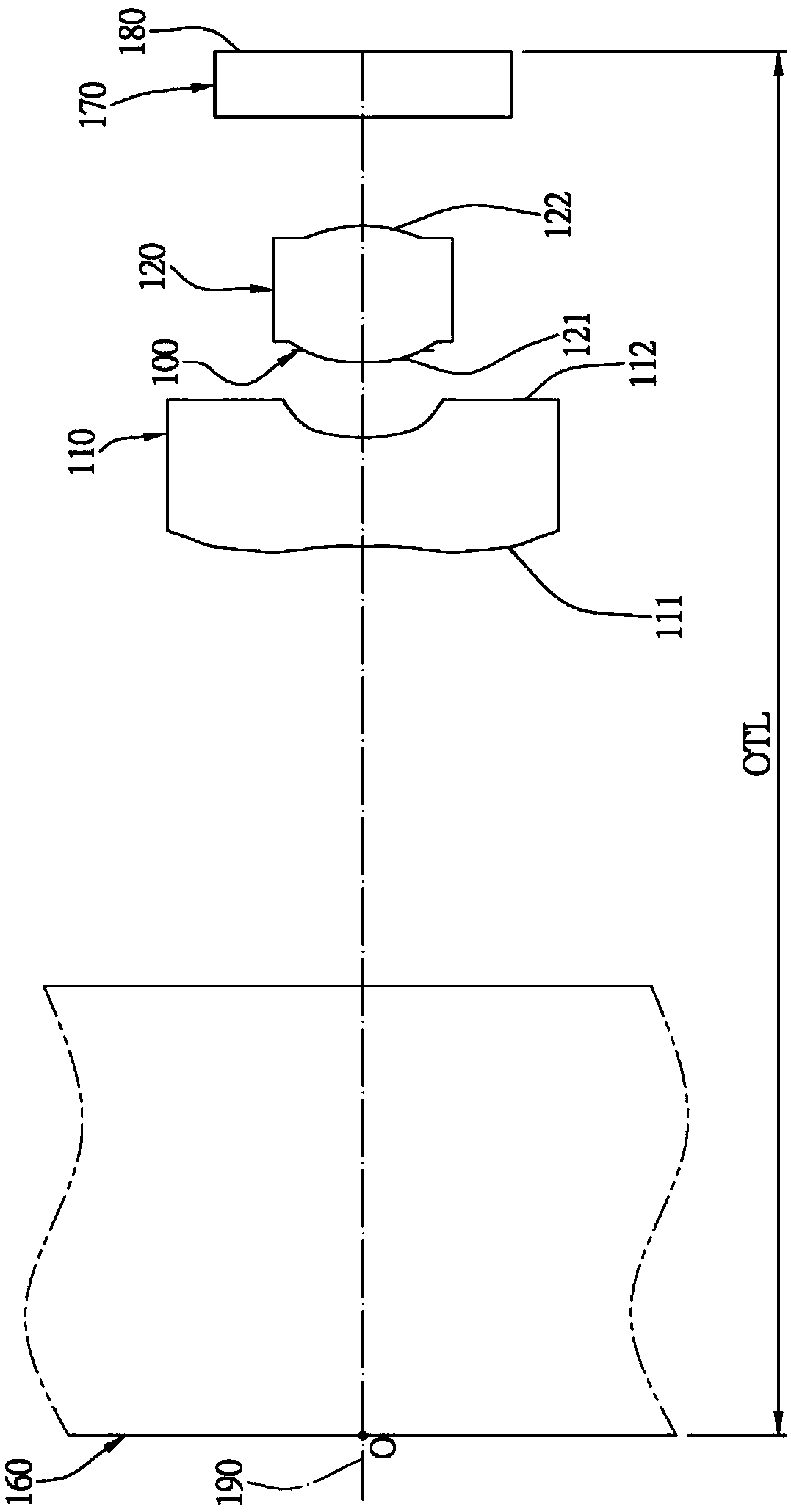
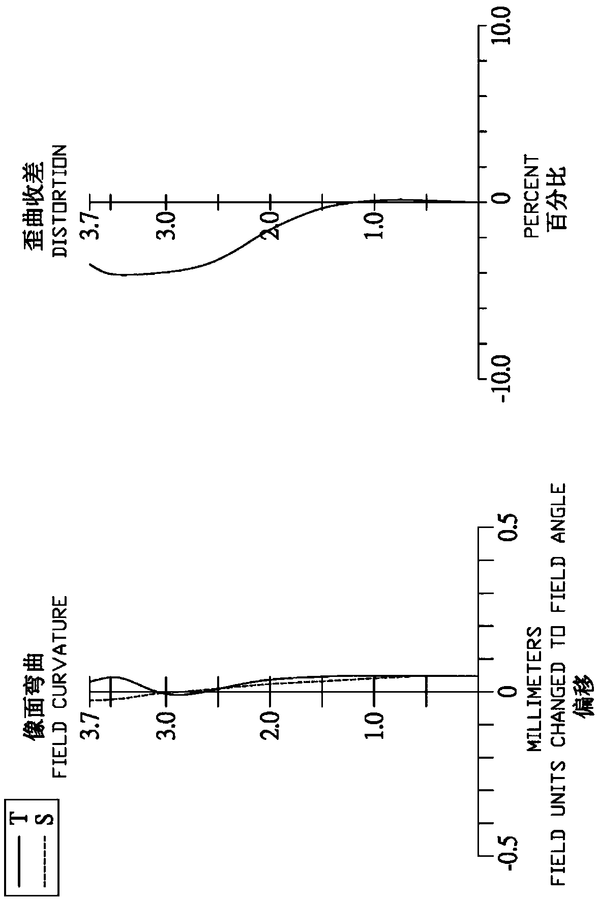
[0069] Please refer to Figure 1A , Figure 1B and Figure 1C ,in Figure 1A A schematic diagram showing a thin imaging lens group according to the first embodiment of the present invention, Figure 1B for Figure 1A A partial enlargement of the . Figure 1C From left to right are the field curvature and distortion aberration curves of the thin imaging lens set of the first embodiment. Depend on Figure 1A and Figure 1B It can be seen that the thin imaging lens group includes a flat plate element 160, a first lens 110, an aperture 100, a second lens 120, an infrared filter 170, and an imaging surface 180 in order from the object side to the image side, wherein the thin imaging lens There are two lenses (110, 120) with refractive power in the group. The aperture 100 is disposed between the first lens 110 and the second lens 120 .

[0070] The plate element 160 is made of glass, and is disposed between an object O and the first lens 110 without affecting the focal length o...

no. 2 example

[0099] Please refer to Figure 2A , Figure 2B and Figure 2C ,in Figure 2A A schematic diagram showing a thin imaging lens group according to the second embodiment of the present invention, Figure 2B for Figure 2A A partial enlargement of the . Figure 2C From left to right are the field curvature and distortion aberration curves of the thin imaging lens set of the second embodiment. Depend on Figure 2A and Figure 2B It can be seen that the thin imaging lens group includes a flat plate element 260, a first lens 210, an aperture 200, a second lens 220, an infrared filter 270, and an imaging surface 280 in order from the object side to the image side, wherein the thin imaging lens There are two lenses (210, 220) with refractive power in the group. The aperture 200 is disposed between the first lens 210 and the second lens 220 .

[0100] The plate element 260 is made of glass, and is disposed between an object O and the first lens 210 without affecting the focal le...

no. 3 example

[0112] Please refer to Figure 3A , Figure 3B and Figure 3C ,in Figure 3A A schematic diagram showing a thin imaging lens group according to a third embodiment of the present invention, Figure 3B for Figure 3A A partial enlargement of the . Figure 3C From left to right are the field curvature and distortion aberration curves of the thin imaging lens set of the third embodiment. Depend on Figure 3A and Figure 3B It can be seen that the thin imaging lens group includes a flat plate element 360, a first lens 310, an aperture 300, a second lens 320, an infrared filter 370, and an imaging surface 380 in order from the object side to the image side, wherein the thin imaging lens There are two lenses (310, 320) with refractive power in the group. The aperture 300 is disposed between the first lens 310 and the second lens 320 .

[0113] The plate element 360 is made of glass, and is disposed between an object O and the first lens 310 without affecting the focal length...


PUM


Abstract

The invention discloses a thin imaging lens group. The thin imaging lens group sequentially comprises a flat plate component, a first lens, a diaphragm and a second lens from an object side to an image side, wherein the flat plate component is made of a glass material, the first lens has negative refractive power, at least one of a surface of the object side and a surface of the image side of thefirst lens is a non-spherical surface, the second lens has positive refractive power, a convex surface is arranged at a position, near an optical axis, of a surface of the object side of the second lens, a convex surface is arranged a position, near the optical axis, of a surface of the image side of the second lens, and at least one of the surface of the object side and the surface of the image side of the second lens is a non-spherical surface. Therefore, a light ray at a large angle is effectively collected, an image in a larger range is received by the thin imaging lens group within an extremely short object distance, and the identification effect is achieved; and meanwhile, the distance between a shot object and the thin imaging lens group is favorably reduced, the size can be effectively reduced, and the miniaturization of the thin imaging lens group is maintained.

Description

technical field [0001] The invention relates to a lens group, in particular to a thin imaging lens group applied to electronic products. Background technique [0002] The biometric system based on the unique biological characteristics of each creature is often used because of its uniqueness, universality, permanence, measurability, convenience, acceptability, and non-deception It can be used on existing mobile devices currently on the market, and can even be used on future electronic devices. However, most of the current biometric identification systems for mobile devices use the capacitor principle. Although it can reduce the size required for the biometric identification system, the circuit structure is too complex, which makes the manufacturing cost too high and the relative unit price of the product is also relatively high. [0003] At present, although there are traditional biometric identification systems that use the principle of optical imaging, such as fingerprint ...

Claims


Application Information

Patent Timeline
IPC IPC(8): G02B13/18
CPCG02B13/003
Inventor 蔡斐欣黄靖昀
Owner NEWMAX TECH
Why Eureka
Try Eureka