
Crystal pulling system and method including crucible and barrier

A technology of barriers and crucibles, applied in the field of single crystal pulling systems, can solve problems such as not being fully satisfactory

Active Publication Date: 2020-01-31
GCL NEW (SHANGHAI) PHOTOVOLTAIC TECH CO LTD
View PDF13 Cites 5 Cited by
  • Summary
  • Abstract
  • Description
  • Claims
  • Application Information

AI Technical Summary

Problems solved by technology

Existing systems for achieving these goals are not yet fully satisfactory

Method used


Image

  • Crystal pulling system and method including crucible and barrier
  • Crystal pulling system and method including crucible and barrier
  • Crystal pulling system and method including crucible and barrier

Examples


Embodiment Construction

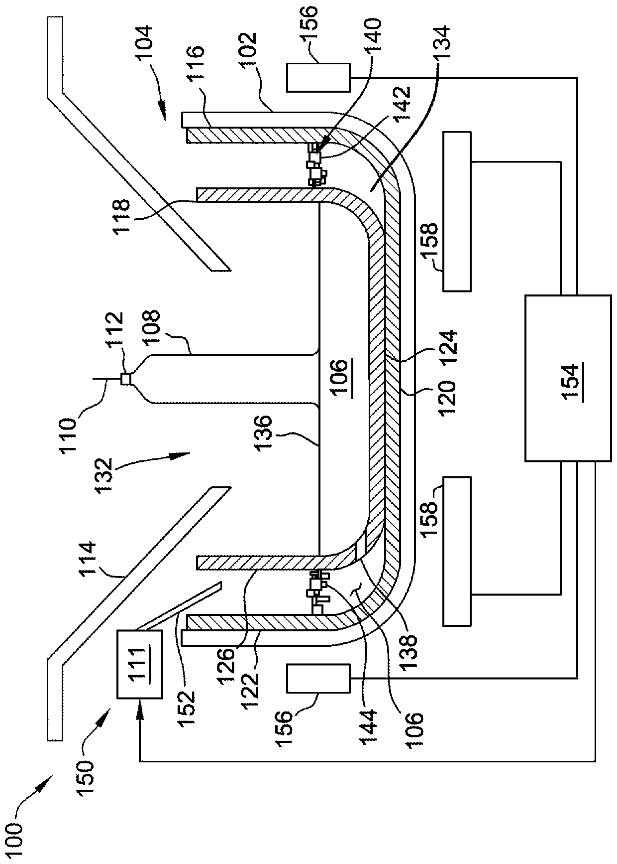
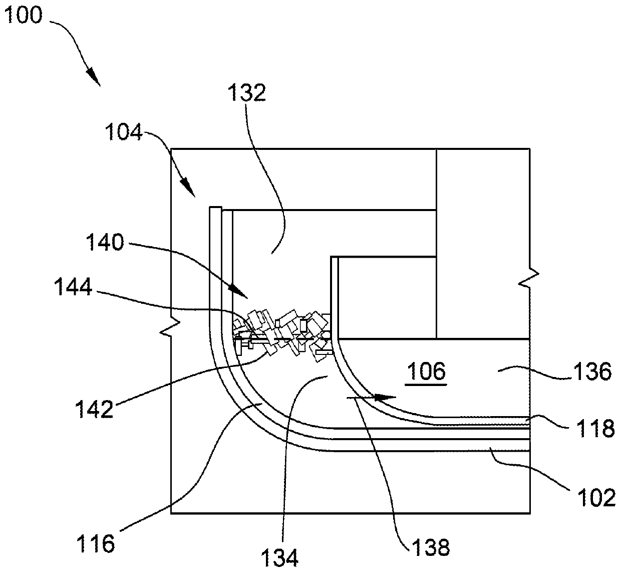
[0015] refer to figure 1 , which schematically illustrates a crystal pulling system, indicated generally at 100 . The crystal pulling system 100 may be used to produce crystal ingots by pulling.

[0016] The illustrated crystal pulling system 100 includes a susceptor 102 supporting a crucible assembly 104 containing a melt 106 of a semiconductor or solar grade material (eg, silicon). Melt 106 may be formed by heating solid feedstock 111 . During operation of system 100 , seed crystal 112 is lowered into melt 106 by crystal puller 110 and then slowly lifted from melt 106 . As the seed crystal 112 is slowly lifted from the melt 106 , the silicon atoms from the melt 106 align themselves with and adhere to the seed crystal 112 to form the ingot 108 . The illustrated system 100 also includes a thermal shield 114 to shield the ingot 108 from radiant heat from the melt 106 and to allow the ingot 108 to solidify.

[0017] Crucible assembly 104 includes a first crucible 116 and a s...


PUM


Abstract

A system for forming an ingot from a melt includes a first crucible defining a cavity for receiving the melt and a second crucible in the cavity. The second crucible separates an outer zone from an inner zone. The second crucible includes a passageway therethrough to allow the melt located within the outer zone to move into the inner zone. The inner zone defines a growth area for the ingot. The system also includes a barrier located within the outer zone to limit movement of the melt through the outer zone. The barrier includes members that are arranged to define a labyrinth for melt flow.

Description

technical field [0001] The present disclosure relates generally to single crystal pulling systems for forming ingots of semiconductor or solar materials from a melt, and more particularly to systems and methods that include crucibles and barriers that limit movement within the melt. Background technique [0002] In the production of single crystal silicon grown by the pulling (CZ) method, polycrystalline silicon is melted in a crucible, such as a quartz crucible, in a crystal pulling device to form a silicon melt. The crystal puller lowers the seed crystal into the melt and slowly lifts the seed crystal out of the melt, causing the melt to solidify on the seed crystal to form the ingot. In the continuous CZ process, polysilicon is added to the melt while the seed crystal is lifted out of the melt. The addition of polysilicon may affect the temperature of the melt and may create disturbances along the surface of the melt. However, the temperature and stability of the melt s...

Claims


Application Information

Patent Timeline
Patent Type & Authority Applications(China)
IPC IPC(8): C30B15/02C30B15/12C30B29/06C30B15/00
CPCC30B15/002C30B15/02C30B15/12C30B29/06
Inventor S·塞佩达R·J·菲利普斯C·V·吕尔斯
Owner GCL NEW (SHANGHAI) PHOTOVOLTAIC TECH CO LTD
Learn More