Eureka AIR delivers breakthrough ideas for toughest innovation challenges, trusted by R&D personnel around the world.

Modular dust removal and denitration integrated apparatus

A modular and catalytic device technology, which is applied in gas treatment, chemical instruments and methods, and dispersed particle filtration, etc., can solve problems such as failure to fully meet standards, equipment efficiency cannot be fully utilized, and equipment cost increases

Pending Publication Date: 2020-02-04
BEIJING GUODIAN LONGYUAN ENVIRONMENTAL ENG
View PDF0 Cites 0 Cited by
  • Summary
  • Abstract
  • Description
  • Claims
  • Application Information

AI Technical Summary

Problems solved by technology

[0002] Nowadays, the requirements for waste gas treatment are becoming more and more stringent, and the waste gas emissions from heavily polluting industries need to be strictly treated before being discharged. Enterprises that need to carry out tail gas treatment have installed denitrification and dust removal equipment, but the total amount of waste gas in non-electric fields is small. The use of a complete set of split-type out-of-stock dust removal equipment not only occupies a large area, but also requires high equipment construction costs, and the efficiency of the equipment after completion cannot be fully utilized, resulting in waste of resources
Moreover, the temperature of the flue gas is generally between 180-280 °C, and it is difficult to select catalysts and dust removal equipment, resulting in poor exhaust gas treatment effect and failure to fully meet the standards. It is necessary to add auxiliary equipment to fully meet the emission standards, which in turn leads to an increase in equipment costs.

Method used


Image

  • Modular dust removal and denitration integrated apparatus
  • Modular dust removal and denitration integrated apparatus
  • Modular dust removal and denitration integrated apparatus

Examples


Embodiment Construction

[0026] The following will clearly and completely describe the technical solutions in the embodiments of the present invention in conjunction with the accompanying drawings. Obviously, the described embodiments are only some of the embodiments of the present invention, not all of them. Based on the embodiments of the present invention, all other embodiments obtained by persons of ordinary skill in the art without making creative efforts belong to the protection scope of the present invention.

[0027] In the description of this patent, it is to be understood that the terms "center", "upper", "lower", "front", "rear", "left", "right", "vertical", "horizontal", The orientation or positional relationship indicated by "top", "bottom", "inner", "outer", etc. is based on the orientation or positional relationship shown in the drawings, and is only for the convenience of describing this patent and simplifying the description, rather than indicating or implying References to devices or...


PUM

PropertyMeasurementUnit
Section sizeaaaaaaaaaa
Diameteraaaaaaaaaa

Abstract

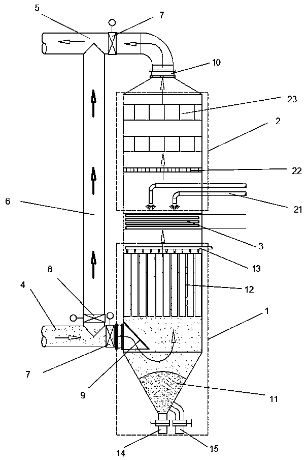
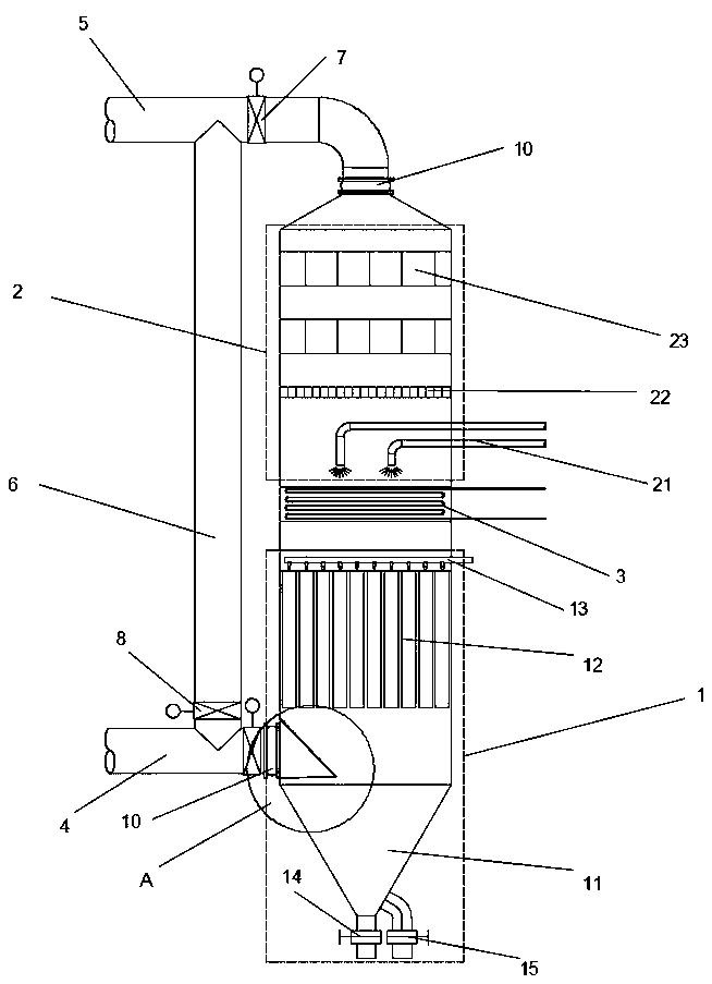
The invention discloses a modular dust removal and denitration integrated apparatus. The apparatus comprises a denitration system and a dust removal system which are respectively arranged at the upperpart and the lower part of the same chamber of a tank body and are separated by a heat exchanger in the middle, the dust removal system is connected with an air inlet channel, and the denitration system is connected with an air outlet channel; the dust removal system comprises a dust removal bucket, a dust remover and a blowing device, and the air inlet channel is connected to the chamber where the dust remover is located; the denitration system comprises a reducing agent injection device, a rectification grid and a catalyst device, and the air outlet channel is arranged at the top end of thedenitration chamber; and a bypass flue gas channel is arranged between the air inlet channel and the air outlet channel and is arranged outside the tank body. The dust removal system and the denitration system are vertically arranged in the same tank body, so that cooperative treatment of dust removal and denitration is realized, and the occupied space of the apparatus is reduced; and the catalyst device is arranged in a modular mode, so the catalyst device and the dust remover with the same area have the same flue gas treatment capacity and can be flexibly arranged to meet different requirements.

Description

technical field [0001] The invention relates to the technical field of air pollution control, in particular to a modular dust removal and denitrification integrated device. Background technique [0002] Nowadays, the requirements for waste gas treatment are becoming more and more stringent, and the waste gas emissions from heavily polluting industries need to be strictly treated before being discharged. Enterprises that need to carry out tail gas treatment have installed denitrification and dust removal equipment, but the total amount of waste gas in non-electric fields is small. The use of a complete set of split-type out-of-stock dust removal equipment not only occupies a large area, but also requires high equipment construction costs, and the efficiency of the equipment after completion cannot be fully utilized, resulting in waste of resources. Moreover, the flue gas temperature is generally between 180-280 °C, and it is difficult to select catalysts and dust removal equi...

Claims


Application Information

Patent Timeline
IPC IPC(8): B01D53/86B01D53/56B01D53/88B01D53/90B01D46/02B01D46/04
CPCB01D53/8631B01D53/90B01D53/88B01D46/023B01D46/04B01D2258/0283
Inventor 王玉龙孙丽姚宣钟洪玲劳俊李晓金
Owner BEIJING GUODIAN LONGYUAN ENVIRONMENTAL ENG
Why Eureka
Eureka Blog
Learn More