
Drilling equipment for industrial machinery production

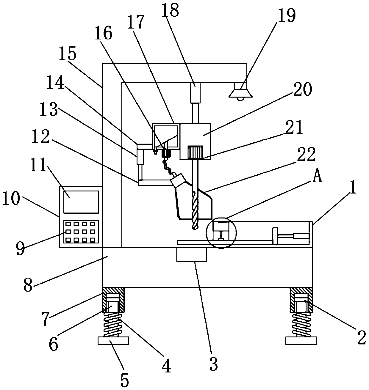
A technology of drilling equipment and industrial machinery, applied in the field of drilling equipment for industrial machinery production, can solve problems such as poor dust suction effect, debris splashing and polluting the environment, and achieve reduced vibration, avoid debris splashing, and good shock absorption effect. Effect

Inactive Publication Date: 2020-02-04
郭和俊
View PDF6 Cites 1 Cited by
  • Summary
  • Abstract
  • Description
  • Claims
  • Application Information

AI Technical Summary

Problems solved by technology

[0004] Based on the technical problems that the existing drilling equipment has a simple structure, poor dust collection effect during the drilling process, and easily causes debris to splash and pollute the environment, the present invention proposes a drilling equipment for industrial machinery production

Method used


Image

  • Drilling equipment for industrial machinery production
  • Drilling equipment for industrial machinery production
  • Drilling equipment for industrial machinery production

Examples


Embodiment 1

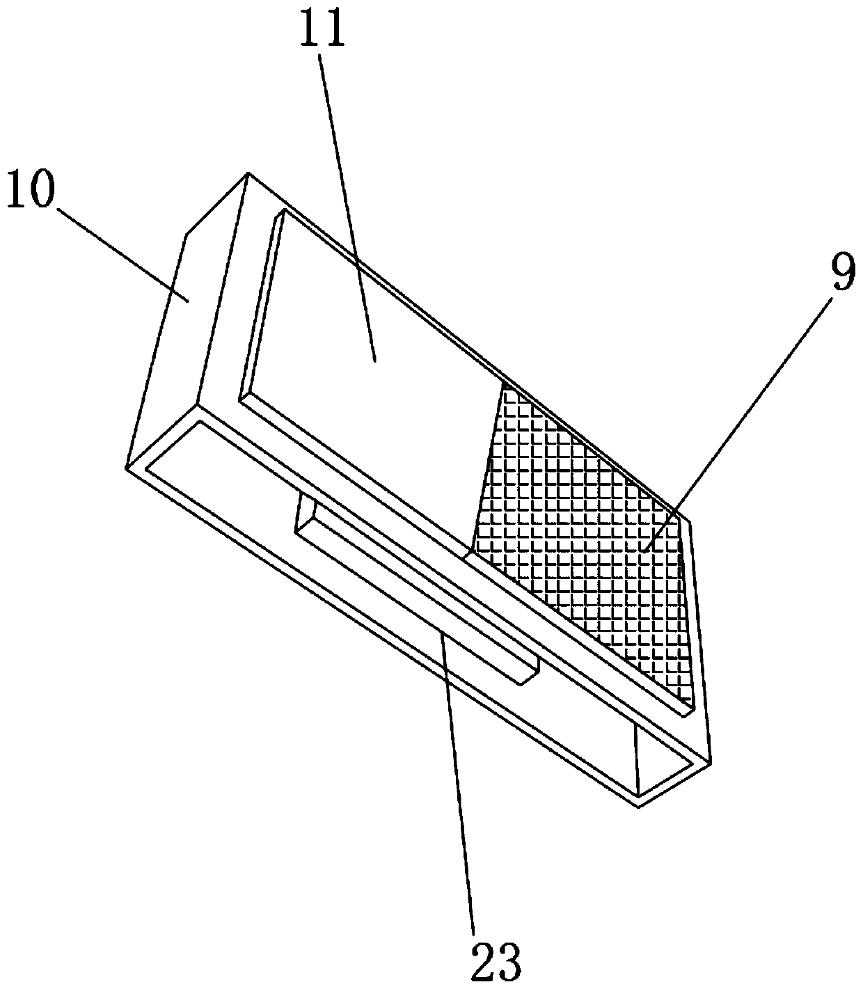
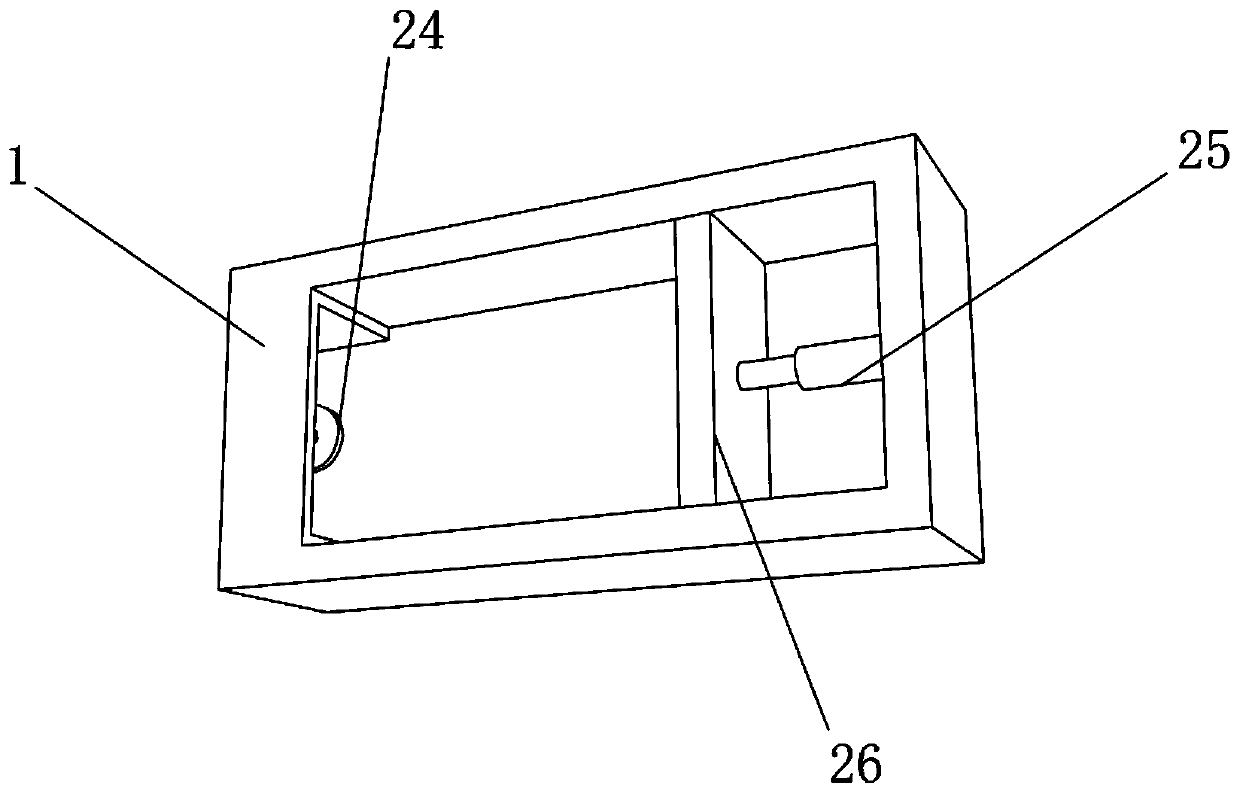
[0027] refer to Figure 1-4 , a drilling device for industrial machinery production, including a base 8, an L-shaped plate 15 is fixed on one side of the top outer wall of the base 8 by screws, and an electric telescopic rod 18 is fixed on the bottom outer wall of the L-shaped plate 15 by screws, and the electric telescopic One end of the rod 18 piston rod is fixed with a fixed block 20 by a screw, and the bottom outer wall of the fixed block 20 is provided with a fixed groove, the inner wall of the fixed groove is fixed with a motor 21 by a screw, and the output shaft of the motor 21 is connected with a drill bit through a coupling , one side outer wall of fixed block 20 is fixed with dust collection box 17 by screw, and the bottom outer wall of dust collection box 17 is fixed with dust suction pump 16 by screw, and the output end of dust suction pump 16 is connected with dust collection box 17, and The input end of the dust collection pump 16 is sleeved with a hose, and the ...

Embodiment 2

[0036] refer to Figure 5 , a kind of drilling equipment for industrial machinery production, compared with embodiment 1, also includes that the top outer wall of L-shaped plate 15 is fixed with solar panel 28 by screw, and the output end of solar panel 28 is connected with solar control by wire The output terminal of the solar controller is connected to the storage battery through wires.

[0037] When in use, the solar panel 28 can generate solar power and store the generated power through the battery to develop new energy, save energy and protect the environment, and conform to the concept of sustainable development of life.


PUM


Abstract

The invention belongs to the technical field of drilling equipment and particularly discloses drilling equipment for industrial machinery production. Aiming to the problems of simple structure, relatively poor dust collection effect in the drilling process and easiness in environmental pollution caused by splashing of debris of existing drilling equipment, the following technical scheme is provided: the drilling equipment for industrial machinery production comprises a base; an L-shaped plate is fixed to one side of the outer wall of the top of the base through a screw; an electric telescopicrod is fixed to the outer wall of the bottom of the L-shaped plate through a screw; a fixed block is fixed at one end of a piston rod of the electric telescopic rod through a screw; a fixed groove isformed in the outer wall of the bottom of the fixed block; a motor is fixed to the inner wall of the fixed groove through a screw; and a drill bit is connected to an output shaft of the motor througha coupling. For the drilling equipment disclosed by the invention, by arranging the motor, the electric push rod and a dust suction pump, the piston rod of the electric push rod can be controlled to shrink, a dust blocking cover is guaranteed to be always in a state of being attached to a steel plate, a good dust blocking effect is exerted, and pollution of the debris to the surrounding environment is avoided.

Description

technical field [0001] The invention relates to the technical field of drilling equipment, in particular to a drilling equipment for industrial machinery production. Background technique [0002] Drilling refers to the operation of machining a hole in a solid material with a drill. Here is a description of the drilling work in the exploration work, as well as the auxiliary tools needed for drilling and some emergency measures. [0003] In geological exploration work, drilling equipment is used to drill a columnar hole with a small diameter and a large depth underground, also known as drilling. Boreholes for oil and gas and groundwater are larger in diameter. The diameter and depth of the drill hole depend on the burial depth of geological minerals and the purpose of the drill hole. In the production process of industrial machinery, it is often necessary to use drilling equipment to drill steel plates. The existing drilling equipment has a simple structure and During the p...

Claims


Application Information

Patent Timeline
IPC IPC(8): B23B47/00B23Q11/00B23Q11/08
CPCB23B47/00B23Q11/00B23Q11/0042B23Q11/08
Inventor 郭和俊
Owner 郭和俊
Learn More