
Rolling brush mechanism and closed space ventilating device thereof

A ventilation device and confined space technology, applied in safety devices, mine/tunnel ventilation, transportation and packaging, etc., can solve the problems of easy blockage of pipelines, high maintenance frequency, downtime, etc., to reduce maintenance frequency and exhaust ducts. Smooth and reduce the effect of tiny particles

Active Publication Date: 2020-02-04
湖南隆回金杏矿业有限责任公司
View PDF17 Cites 3 Cited by
  • Summary
  • Abstract
  • Description
  • Claims
  • Application Information

AI Technical Summary

Problems solved by technology

[0003] However, this type of confined space ventilation device generally simply reverses the air flow, and the underground dust, dust, etc. are relatively large, especially in the air duct, whose wind force can blow small stones, so solid debris blocks the ventilation pipe is commonplace
In order to ensure the normal operation of ventilation devices in confined spaces, it is generally necessary to regularly overhaul the air ducts, and because the ducts are easy to block, the frequency of overhauls has to be relatively high, sometimes more than three times a week
This obviously greatly increases manpower input, and it needs to be shut down during the maintenance process. Once shut down, the ventilation area must be shut down, which has a great impact on the mining progress

Method used


Image

  • Rolling brush mechanism and closed space ventilating device thereof
  • Rolling brush mechanism and closed space ventilating device thereof
  • Rolling brush mechanism and closed space ventilating device thereof

Examples


Embodiment Construction

[0047] The following will clearly and completely describe the technical solutions in the embodiments of the present invention with reference to the drawings in the embodiments of the present invention.

[0048] In describing the present invention, it should be understood that the terms "upper", "lower", "front", "rear", "left", "right", "top", "bottom", "inner", " The orientation or positional relationship indicated by "outside", etc. is based on the orientation or positional relationship shown in the drawings, and is only for the convenience of describing the present invention and simplifying the description, rather than indicating or implying that the referred device or element must have a specific orientation, so as to Specific orientation configurations and operations, therefore, are not to be construed as limitations on the invention.

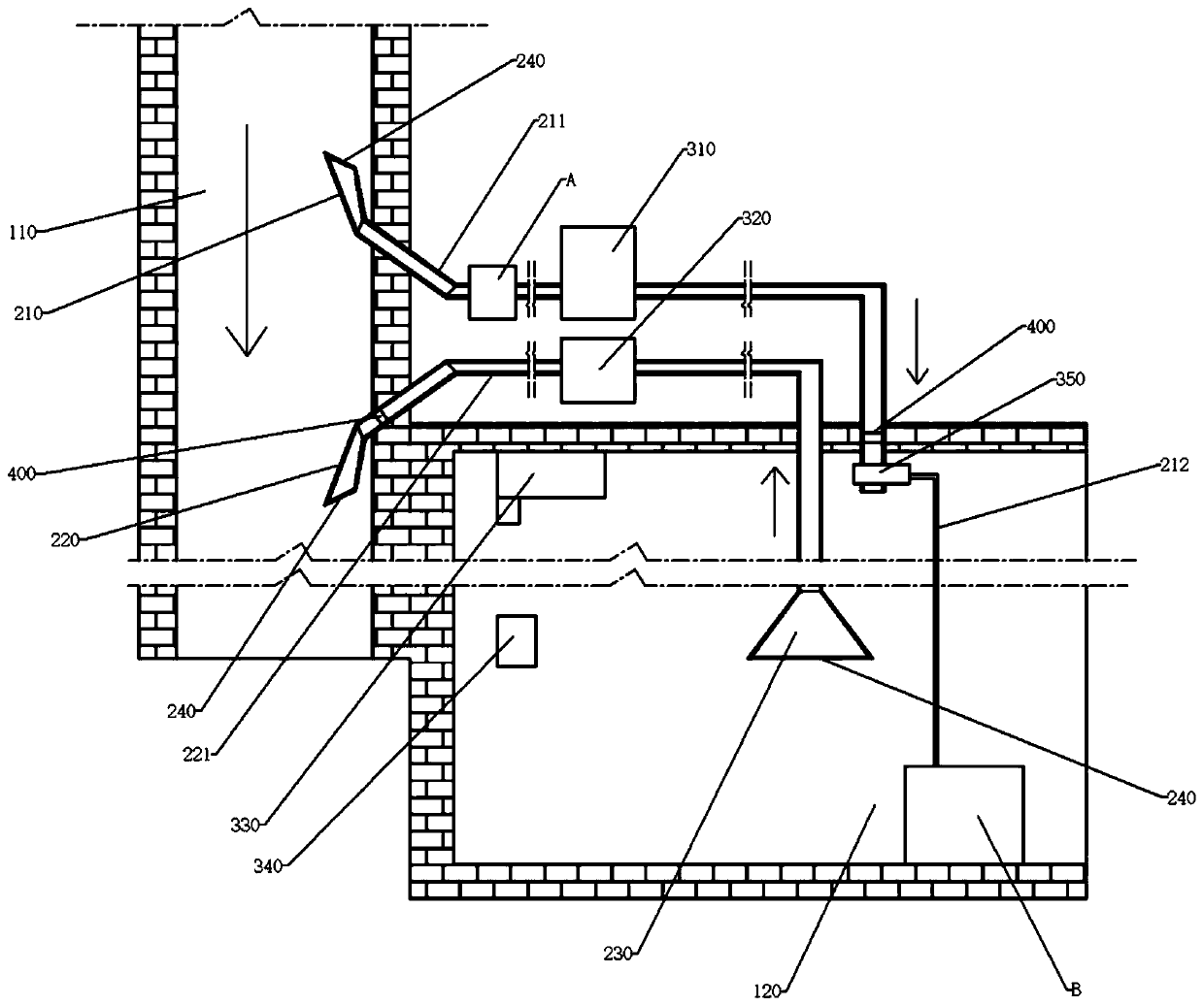
[0049] see Figure 1-Figure 11 , a ventilation device for a confined space, comprising an air inlet pipe 211 and an air exhaust pipe 221...


PUM


Abstract

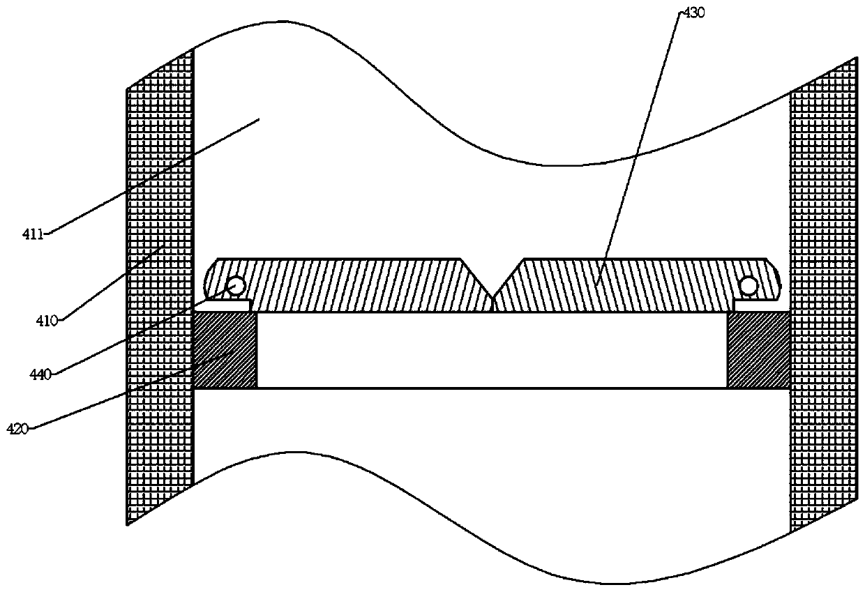
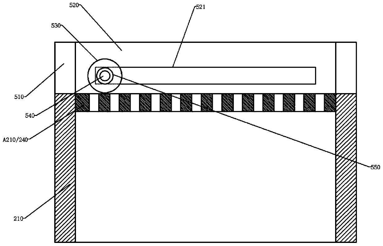
The invention discloses a rolling brush mechanism and a closed space ventilating device thereof. The closed space ventilating device comprises an air inlet pipeline and an air exhaust pipeline, wherein one end of the air inlet pipeline and one end of the air exhaust pipeline are arranged in an underground air channel and are provided with an air inlet bin and an air exhaust bin respectively; the other end of the air inlet pipeline and the other end of the air exhaust pipeline are arranged in a ventilating area, and an air exhaust wind bin is arranged at the end, arranged in the ventilating area, of the air exhaust pipeline; the air inlet pipeline and the air exhaust pipeline are provided with an air inlet fan and an air exhaust fan respectively, and the air inlet fan and the air exhaust fan are used for forming air convection in the air inlet pipeline and the air exhaust pipeline respectively; and the upper end parts of the air inlet bin, the air exhaust bin and the air exhaust wind bin are separated by grids. According to the mechanism and the device, the ventilating area is further provided with a washing device, the air inlet pipeline is further provided with a dust removing device, the dust removing device is provided with a differential pressure mechanism, the dust removing device, the air inlet pipeline and the air exhaust pipeline are provided with rolling brush mechanism bodies, so that brushing and dredging of the grids, a first dust removing net and a second dust removing net are achieved through the rolling brush mechanism bodies.

Description

technical field [0001] The invention relates to ventilating equipment such as underground mines and tunnels, in particular to a rolling brush mechanism and a ventilating device for a closed space thereof. Background technique [0002] In the design of underground ventilation, although there are dedicated air ducts for ventilation, this design can solve the ventilation problems of most roadways. However, for some newly developed mining areas and emergency refuge areas, due to the untimely layout of facilities or the design of refuge spaces, the ventilation in these areas will be seriously delayed or even not ventilated. However, there are many harmful gases in the underground, such as carbon monoxide, methane, sulfur dioxide, etc., and there are more germs. Therefore, in order to ensure the air circulation in this area, it is generally necessary to install a ventilation device for ventilating the enclosed space. Its principle is mainly to connect the air duct with this area ...

Claims


Application Information

Patent Timeline
IPC IPC(8): E21F1/00E21F1/04E21F1/08E21F3/00E21F5/02A61L9/20B01D46/00B01D46/12
CPCE21F1/00E21F1/003E21F1/04E21F1/08E21F5/02E21F3/00B01D46/0002B01D46/12A61L9/20B01D46/62B01D46/681
Inventor 陈宝宝
Owner 湖南隆回金杏矿业有限责任公司
Learn More