Fan structure capable of increasing air inlet amount, evaporator component capable of increasing air inlet amount and noise reduction humidifier

A technology of air intake and humidifier, applied in air humidification system, components of pumping device for elastic fluid, pump components, etc., can solve the high water quality requirements of ultrasonic atomizing humidifiers and high safety performance requirements of electric heating humidifiers , The humidification rate of the humidifier is not high, etc., to achieve the effect of ensuring the humidification efficiency, improving the stability of the air supply, and reducing the setting of the air duct

Pending Publication Date: 2020-02-04
CHENGDU AIMBON INTELLIGENT TECH CO LTD
View PDF0 Cites 2 Cited by
  • Summary
  • Abstract
  • Description
  • Claims
  • Application Information

AI Technical Summary

Problems solved by technology

[0002] A humidifier is a device that increases indoor humidity. It is mainly used to increase indoor air humidity. It is commonly used in living rooms or small offices, so that people can live or work in an air environment with suitable humidity and avoid various physical discomforts caused by dry air. There are many types of existing humidifiers, such as ultrasonic atomization humidifiers and electric heating humidifiers. Although the ultimate purpose of various humidifiers is to increase indoor air humidity, there are different advantages and disadvantages in various humidifiers. Some humidifiers The humidification rate per unit volume is not high, some humidifiers consume high power when moisture is vaporized, and some humidifiers can produce a limited amount of humidification per unit power consumption; for example, electric humidifiers have high safety performance requirements, and ultrasonic fog Humidifiers have higher water quality requirements
[0003] The most suitable for the market is the natural evaporation type humidifier. The evaporation device currently on the market is submerged below the water surface of the water storage tank. When working, the evaporator rotates, and the airflow driven by the fan passes through the evaporator, so that the humid air flows to the outside. To achieve humidification, the evaporation principle is to use the natural evaporation of water; because the evaporation device is soaked in the water tank for a long time and is in contact with water for a long time, it is easy to breed bacteria, so the evaporation device that uses non-consumable materials needs to be cleaned regularly, and the evaporation device that uses consumable materials needs to be replaced regularly

Method used


Image

  • Fan structure capable of increasing air inlet amount, evaporator component capable of increasing air inlet amount and noise reduction humidifier
  • Fan structure capable of increasing air inlet amount, evaporator component capable of increasing air inlet amount and noise reduction humidifier
  • Fan structure capable of increasing air inlet amount, evaporator component capable of increasing air inlet amount and noise reduction humidifier

Examples


Embodiment 1

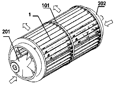
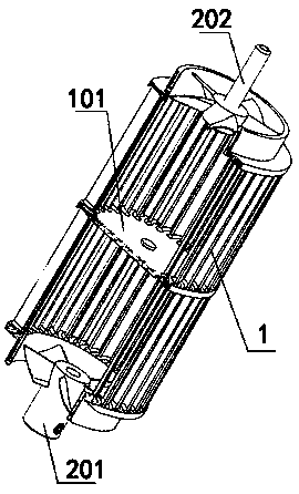
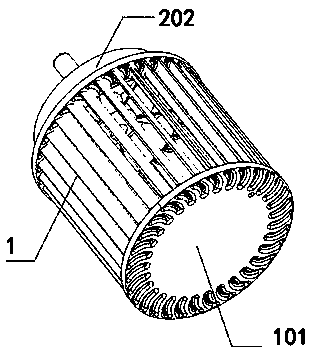
[0040] refer to figure 1 , figure 2 , image 3 As shown, one embodiment of the present invention is a fan structure for increasing air intake, including a cross-flow fan 1, wherein the cross-flow fan 1 is an existing cross-flow fan, and the air flow passes through the impeller of the cross-flow fan 1 to realize air supply. Because the blades of the cross-flow fan 1 are subjected to two forces, the airflow can reach a long distance, but the airflow is forced to turn inside the impeller, so the pressure head loss is relatively large, resulting in low air supply efficiency. The fan 1 is provided with an air supply area, through which the air flow is poured, so that the blades of the cross-flow fan 1 can take away part of the air flow once a force is applied, thereby improving the air supply efficiency.

[0041] Normally, in order to ensure sufficient air supply, the impeller of the cross-flow fan 1 needs to run at high speed. However, when the impeller rotates, the airflow ent...

Embodiment 2

[0044] Based on the above-mentioned embodiment, another embodiment of the present invention is that the middle part of the cross-flow fan 1 is provided with a baffle 101, wherein the baffle 101 has a plurality of blade openings, and the baffle 101 is inserted into the cross-flow fan through the blade openings. 1, and fixed in the middle of the cross-flow fan 1, the baffle 101 is used to form two air supply areas inside the cross-flow fan 1.

[0045] Among them, there are many ways to fix the baffle 101, such as hot melt glue fixing, pin limit, etc.; through two air supply areas corresponding to the first axial flow fan 201 and the second axial flow fan 202, the first axial flow The airflow conveyed by the fan 201 and the second axial flow fan 202 enters different air supply areas without affecting each other, preventing the first axial flow fan 201 and the second axial flow fan 202 from reversely conveying the airflow and causing turbulent flow in the air supply area; thus It is...

Embodiment 3

[0047] Based on the above examples, refer to figure 1 As shown, another embodiment of the present invention is that the first axial flow fan 201 and the second axial flow fan 202 are coaxially arranged with the cross flow fan 1, wherein the first axial flow fan 201 and the second axial flow fan 202 It is an existing axial flow fan, and its first axial flow fan 201 and second axial flow fan 202 outer diameter size is compatible with the cross flow fan 1 side wall inner diameter size, and its first axial flow fan 201 and second axial flow fan The blades of 202 are directed in the opposite direction, so that when the blades of the first axial flow fan 201 and the blades of the second axial flow fan 202 rotate in the same direction, the direction of gas flow is opposite; The blower fan 1, the first axial flow fan 201 and the second axial flow fan 202 rotate; when the first axial flow fan 201, the second axial flow fan 202 and the cross flow fan 1 are coaxially arranged, the rotati...


PUM


Abstract

The invention discloses a fan structure capable of increasing the air inlet amount, an evaporator component capable of increasing the air inlet amount and a noise reduction humidifier. The fan structure comprises a cross-flow fan, and an air supply area is arranged in the cross-flow fan. A first axial flow fan and a second axial flow fan are correspondingly mounted at the two ends of the cross-flow fan. The air supply directions of the first axial flow fan and the second axial flow fan are both facing the interior of the cross-flow fan. The fan structure is used for being mounted in the evaporator component so as to reduce the rotating speed and noise of a fan while the humidification efficiency is ensured.

Description

technical field [0001] The invention relates to the field of humidification equipment, in particular to a fan structure for increasing air intake, an evaporation device and a noise reduction humidifier. Background technique [0002] A humidifier is a device that increases indoor humidity. It is mainly used to increase indoor air humidity. It is commonly used in living rooms or small offices, so that people can live or work in an air environment with suitable humidity and avoid various physical discomforts caused by dry air. There are many types of existing humidifiers, such as ultrasonic atomization humidifiers and electric heating humidifiers. Although the ultimate purpose of various humidifiers is to increase indoor air humidity, there are different advantages and disadvantages in various humidifiers. Some humidifiers The humidification rate per unit volume is not high, some humidifiers consume high power when moisture is vaporized, and some humidifiers can produce a limit...

Claims


Application Information

Patent Timeline
Patent Type & Authority Applications(China)
IPC IPC(8): F04D25/16F04D17/04F04D19/00F04D29/66F24F6/06F24F13/24
CPCF04D17/04F04D19/002F04D25/166F04D29/661F24F6/06F24F13/24F24F2013/247
Inventor 皮体斌
Owner CHENGDU AIMBON INTELLIGENT TECH CO LTD
Why Eureka
Try Eureka