
Portable detection device for blockage of exposed filling pipeline, and dredging method

A technology for detection devices and pipelines, which is applied in the directions of measuring devices, geophysical measurements, and processing detection response signals, etc., which can solve problems such as limiting the conveying speed of filling materials, reducing filling efficiency, and interruption of construction, and achieve rapid and efficient dredging and dredging effects Good, high detection efficiency

Pending Publication Date: 2020-02-04
CHINA UNIV OF MINING & TECH
View PDF0 Cites 5 Cited by
  • Summary
  • Abstract
  • Description
  • Claims
  • Application Information

AI Technical Summary

Problems solved by technology

[0003] However, during the operation of the filling system, the most prominent defect is that the filling efficiency cannot keep up with the resource extraction efficiency, resulting in low filling and mining efficiency
The reasons for the low filling efficiency are not only the filling materials themselves, such as paste and colloid filling materials, which take a certain amount of time to harden after filling, but also the blockage of the filling pipe is another important factor that reduces the filling efficiency. The blockage of the filling pipe will not only cause construction interruption, look for 1. It takes time and effort to clear the blockage point, and it will limit the conveying speed of the filling material to a certain extent
[0004] Commonly used methods for finding blockages include segmental dismantling and pressure monitoring, which are possible for short-distance filling pipelines, but many difficulties need to be overcome. For long-distance filling material transportation pipelines, These methods will be more difficult to implement and will greatly increase the operating cost. Therefore, there is currently no reliable and simple detection device and a fast and efficient dredging method to solve the problem of blockage of the exposed filling pipes such as paste and colloid.

Method used


Image

  • Portable detection device for blockage of exposed filling pipeline, and dredging method
  • Portable detection device for blockage of exposed filling pipeline, and dredging method
  • Portable detection device for blockage of exposed filling pipeline, and dredging method

Examples


Embodiment Construction

[0032] The present invention will be further described below in conjunction with accompanying drawing.

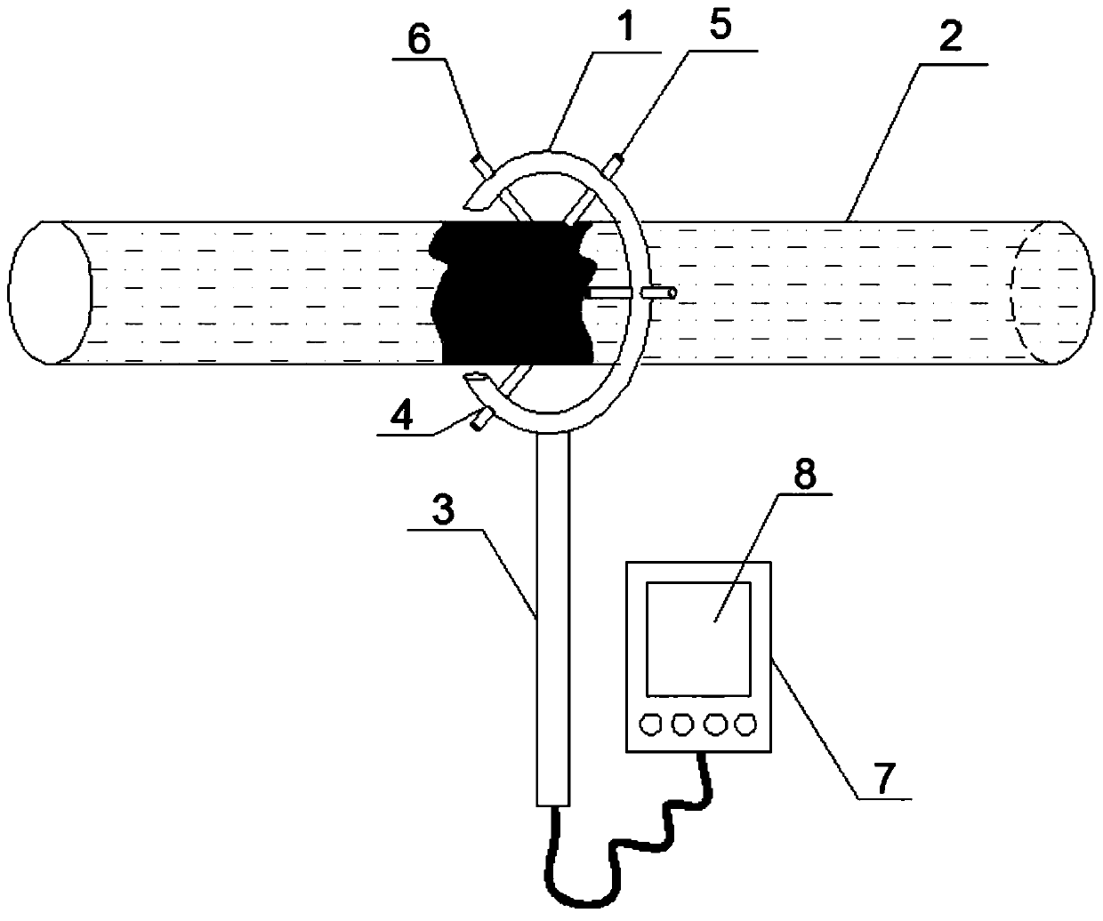
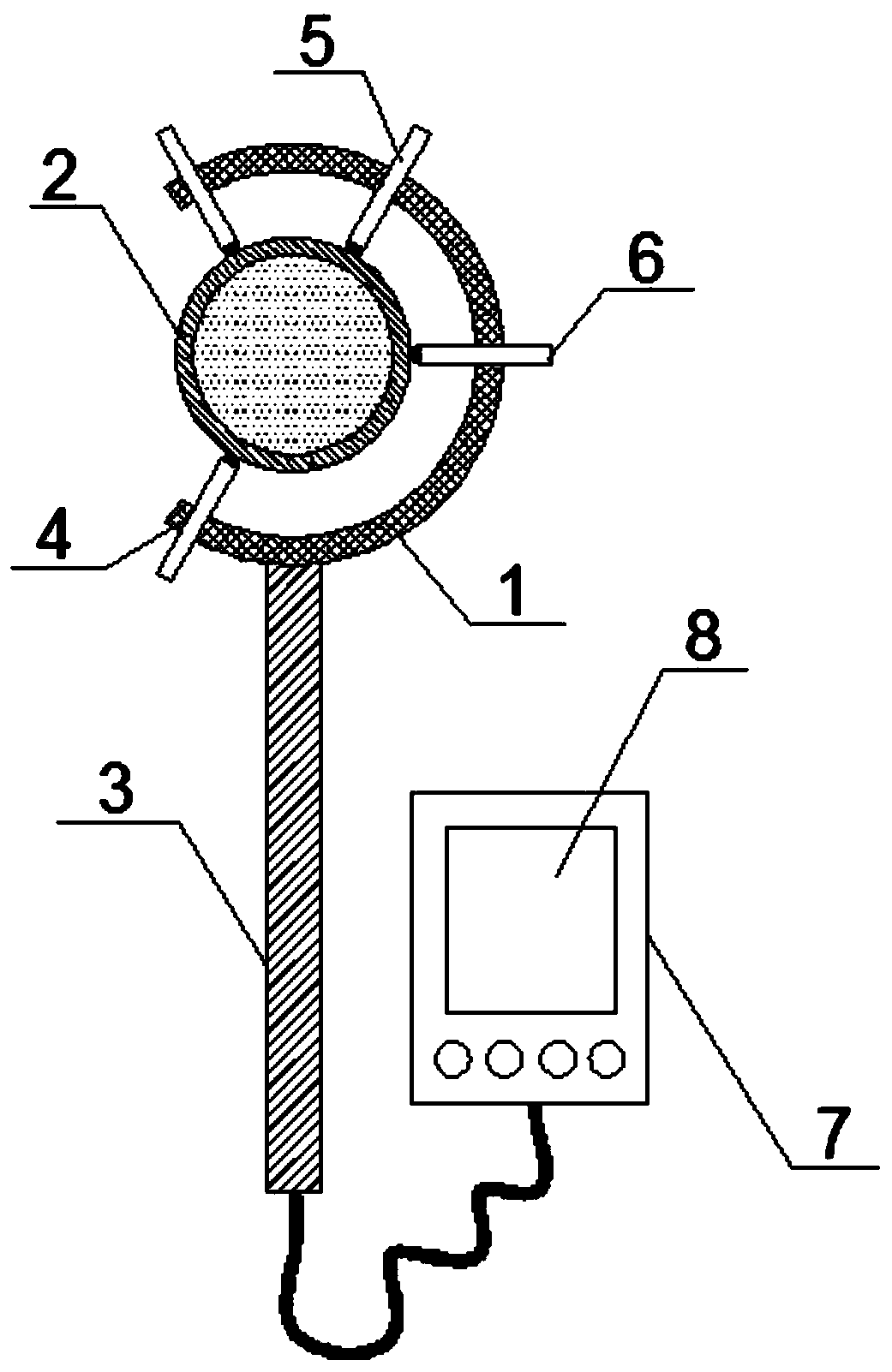
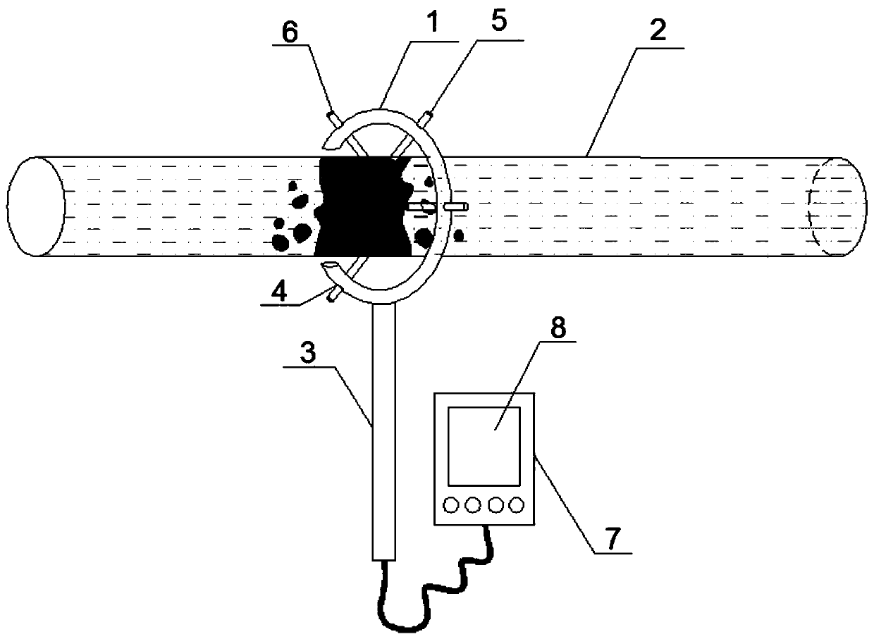
[0033] Such as figure 1 with figure 2 As shown, a portable detection device for the blockage of an exposed filling pipeline includes a C-shaped split ring 1 whose width at the open end is not less than the outer diameter of the pipe 2, and the inner diameter of the split ring 1 is greater than the outer diameter of the pipe 2; the lower end of the split ring 1 connected with handle 3;

[0034] A plurality of threaded mounting holes 4 are provided on the split ring 1, and an ultrasonic receiving probe 5 is installed in one of the mounting holes 4, and ultrasonic resonance contacts 6 are respectively installed in the remaining mounting holes 4. The ultrasonic receiving probe 5 and the ultrasonic wave The resonance contact 6 is slidingly matched with the outer wall of the pipeline 2; the ultrasonic receiving probe 5 and the ultrasonic resonance contact 6 are both connected ...


PUM


Abstract

A portable detection device for blockage of an exposed filling pipeline comprises a C-shaped split ring, wherein the split ring is provided with a plurality of threaded mounting holes, and ultrasonicreceiving probes and ultrasonic resonance contacts are inserted into the mounting holes, are in sliding cooperation with the outer wall of the pipeline, and are respectively connected to an integratedcontroller. A dredging method for blockage of an exposed filling pipeline comprises the following steps of collecting reference data; determining the location of the blockage; and dredging the blockage: for the location of the blockage, using the resonance frequency of the corresponding filling material after curing, turning on the ultrasonic variable frequency vibration component and the ultrasonic vibration test component to continuously scan the outer wall of the pipeline at the blocked position, and breaking the solids in the pipeline until the pipeline is dredged. Requiring no other changes on the original pipeline system, the device and method can easily detect and dredge the blockage in the pipeline.

Description

technical field [0001] The invention relates to a pipeline detection device and a dredging method, in particular to a portable detection device and a dredging method for the clogging of an exposed filling pipeline, and belongs to the technical field of clogging detection and dredging of an exposed filling pipeline. Background technique [0002] Compared with traditional mining methods, filling mining has advantages such as reducing waste rock discharge, avoiding surface deformation and subsidence, groundwater loss, and low-loss mining. It is an environmentally friendly and long-term resource-saving method. coal mining methods. [0003] However, during the operation of the filling system, the most prominent defect is that the filling efficiency cannot keep up with the resource extraction efficiency, resulting in low filling and mining efficiency. The reasons for the low filling efficiency are not only the filling materials themselves, such as paste and colloid filling materi...

Claims


Application Information

Patent Timeline
IPC IPC(8): G01V1/00G01N29/04G01N29/46
CPCG01N29/04G01N29/46G01N2291/023G01V1/00
Inventor 李桂臣许嘉徽孙长伦梁巨理荣浩宇孙元田张苏辉
Owner CHINA UNIV OF MINING & TECH
Learn More