Touch electronic knob and wiring structure thereof

A wiring structure and electronic technology, applied in circuits, electrical switches, electrical components, etc., can solve problems such as small application range, and achieve the effect of reducing resistance increase, product structure stability and life improvement.

Pending Publication Date: 2020-02-04
昆山峰实电子外观应用科技有限公司
View PDF0 Cites 1 Cited by
  • Summary
  • Abstract
  • Description
  • Claims
  • Application Information

AI Technical Summary

Problems solved by technology

However, since the capacitive sensing circuit is generally a single-sliding design, the applicable range is smaller than that of the mechanical knob

Method used


Image

  • Touch electronic knob and wiring structure thereof
  • Touch electronic knob and wiring structure thereof
  • Touch electronic knob and wiring structure thereof

Examples


Embodiment 1

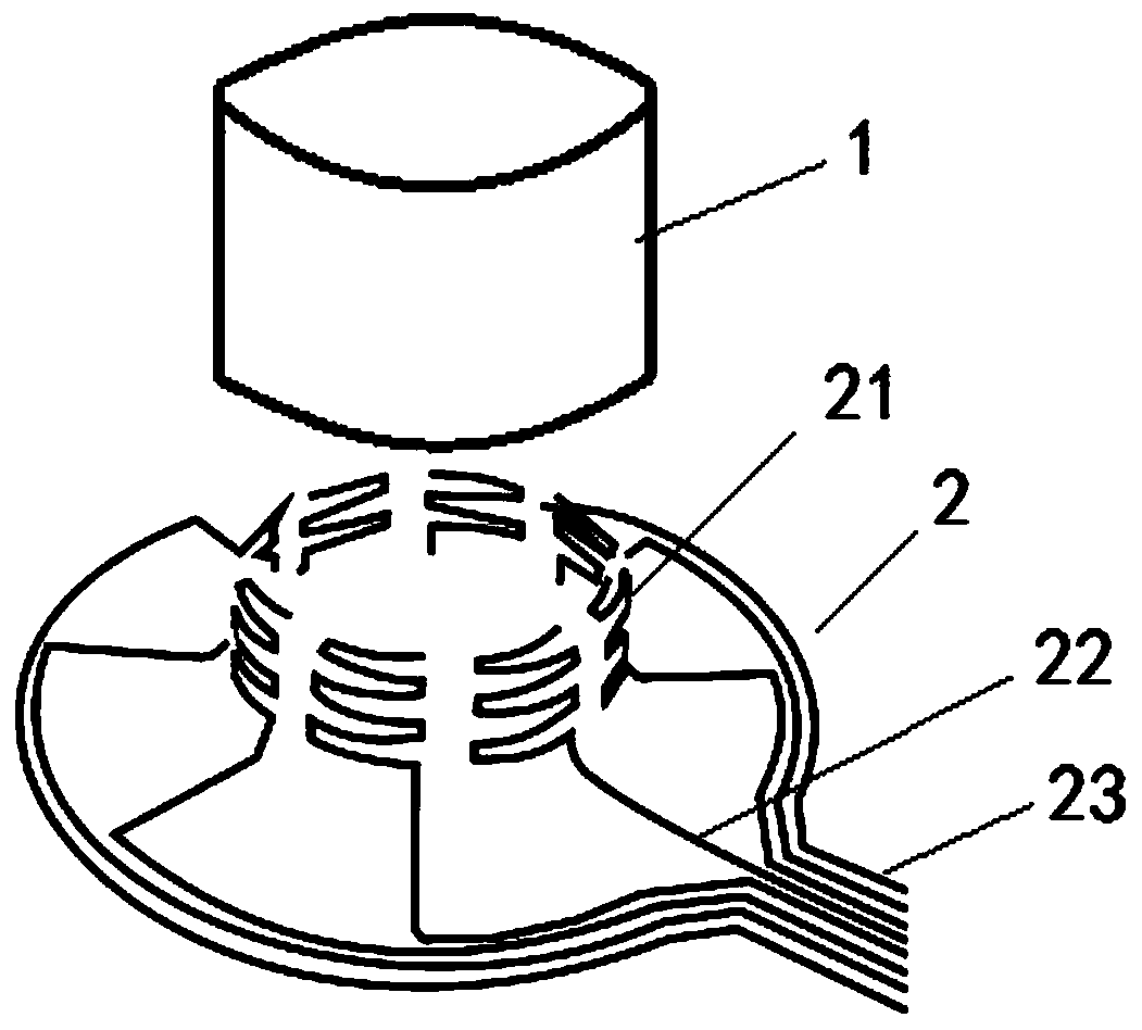
[0033] This embodiment is a wiring structure of a touch-sensitive electronic knob, refer to figure 1 As shown, the touch-sensitive electronic knob includes an operation button 1 and an induction circuit unit 2, and the induction circuit unit 2 includes a plurality of capacitive sensing lines; the operation button 1 is provided with a hollow accommodation part;

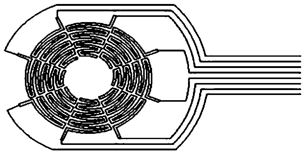
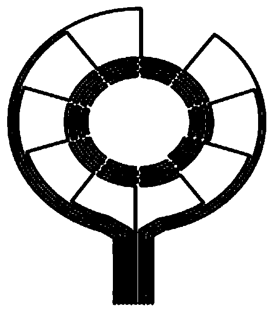
[0034] Each capacitive sensing circuit includes a rotary sensing part 21 and a signal conducting part 22 connected to each other, and the opposite end of the signal conducting part connected to one end of the rotary sensing part is the sensing output terminal 23; the signal conducting parts of a plurality of capacitive sensing lines are located in the same conducting plane , the operation button is located on one side of the conduction plane, one end of the hollow accommodation part is open and faces the conduction plane, each rotation sensing part 21 is bent toward the side where the operation button 1 is located into ...

Embodiment 2

[0047] This embodiment is a touch-sensitive electronic knob applying the wiring structure of Embodiment 1. The touch-sensitive electronic knob includes an operation button, an induction circuit unit and a functional drive circuit unit; refer to Image 6 Shown:

[0048] The sensing circuit unit includes a plurality of capacitive sensing circuits and a capacitive touch processor; the plurality of capacitive sensing circuits are wired according to the wiring structure described in the first aspect; the capacitive touch processor includes a plurality of touch signal input terminals and signal output terminals; The sensing output ends of the capacitive sensing circuit are respectively connected to a signal input end of the capacitive touch processor;

[0049] The functional driving circuit unit includes a controller, the controller includes a touch signal input end and a plurality of control signal output ends, the touch signal input end is connected to the signal output end of the...


PUM


Abstract

The invention discloses a touch control type electronic knob and a wiring structure thereof, the touch control type electronic knob comprises an operation knob and an induction circuit unit, and the induction circuit unit comprises a plurality of capacitance induction circuits; a hollow accommodating part is arranged in the operating knob; each capacitive sensing circuit comprises a rotation sensing part and a signal transmission part which are connected with each other; the signal conduction parts of the capacitive sensing circuits are located in the same conduction plane, the operation button is located on one side of the conduction plane, one end of the hollow containing part is open and faces the conduction plane, and the rotation sensing parts are bent into the hollow containing parttowards the side where the operation button is located and evenly arranged on the periphery of the hollow containing part. According to the invention, the capacitive sensing of the control signal canbe realized without carrying out entity rotation operation on the knob, so that the operation control of the equipment can be realized according to the change of the sensing capacitance, the structural stability of the product is improved, and the service life of the product is prolonged.

Description

technical field [0001] The invention relates to the technical field of control knobs, in particular to a touch-sensitive electronic knob and its wiring structure. Background technique [0002] The control knobs of existing automobiles, home appliances and other consumer electronic products are mostly mechanical knobs, which can control the switching of the operating state of the equipment through the rotation of the operating knobs. However, mechanical knobs are generally assembled with multiple parts, and the structure is relatively complicated. The life of the mechanical knob is also limited by the strength and toughness of the rotating shaft and other components, so it is difficult to guarantee the reliability of long-term operation. [0003] The design of the capacitive touch knob can make up for the defect in the service life of the mechanical knob, which realizes the operation control of the device by setting the capacitive sensing line in the touch screen. However, s...

Claims


Application Information

Patent Timeline
IPC IPC(8): G06F3/044H01H19/14
CPCG06F3/044H01H19/14
Inventor 李昭松何宗勋高谊恬
Owner 昆山峰实电子外观应用科技有限公司
Why Eureka
Try Eureka