
A coupling cavity traveling wave tube energy transmission structure and its assembly method

An assembly method and traveling wave tube technology, which are applied to the coupling device of transit time type electron tubes, the manufacture of discharge tubes/lamps, the manufacture of electrode systems, etc., can solve the problems that the reliability of components cannot meet the use requirements of traveling wave tubes, etc. To achieve good air tightness, ensure the use of requirements, the system impedance matching effect is good

Active Publication Date: 2022-03-25
NANJING SANLE GROUP
View PDF0 Cites 0 Cited by
  • Summary
  • Abstract
  • Description
  • Claims
  • Application Information

AI Technical Summary

Problems solved by technology

However, for parts with special shapes and structures, special assembly steps and welding sequences are required, otherwise the reliability of the parts cannot meet the requirements for the use of traveling wave tubes

Method used


Image

  • A coupling cavity traveling wave tube energy transmission structure and its assembly method
  • A coupling cavity traveling wave tube energy transmission structure and its assembly method
  • A coupling cavity traveling wave tube energy transmission structure and its assembly method

Examples


Embodiment 1

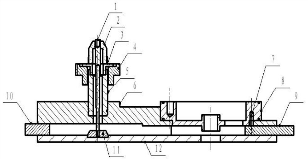
[0035] Such as figure 1 As shown, a coupling cavity traveling wave tube energy transmission structure, which includes: an inner conductor 1, a window ceramic 2 welded outside the inner conductor 1, a sealing ring 3 welded on the lower end of the window ceramic 2, a sealing ring 3 welded on the The outer conductor 5 at the lower end, the fastening screw sleeve 4 set outside the sealing ring 3 and the outer conductor 5;

[0036] The lower end of the inner conductor 1 passes through the window porcelain 2, the sealing ring 3 and the outer conductor 5 and is then inserted into the antenna slot provided on the waveguide cover plate 12. A circular antenna 11 is placed in the antenna slot, and the lower end of the inner conductor 1 passes through the antenna slot. Fix in the antenna slot after crossing the circular antenna 11;

[0037] After the lower end of the outer conductor 5 and the contact surface of the impedance transformer 7 are riveted along the circumference, they are wel...

Embodiment 2

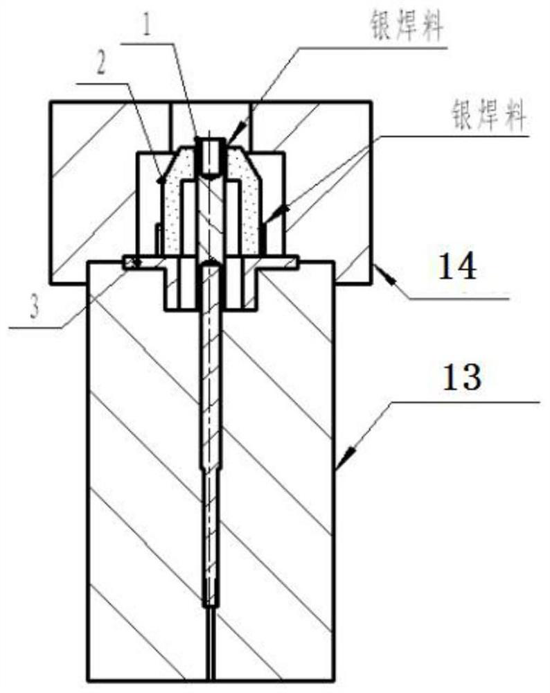
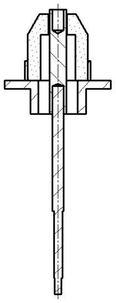
[0041] Such as Figure 2 to Figure 9 , a method for assembling an energy transmission structure of a coupled cavity traveling wave tube, comprising the following steps:

[0042] Step a: First place the sealing ring 3 in the first welding mold 13, then put the window ceramic 2 outside the inner conductor 1, place the window ceramic 2 on the sealing ring 3, and let the lower end of the inner conductor 1 pass through After the sealing ring 3 is inserted into the first welding mold 13; then the second welding mold 14 is put on the first welding mold 13, and the second welding mold 14 is placed on the outer periphery of the window porcelain 2; then the inner conductor 1, the sealing ring 3 and the window porcelain 2 are welded by silver brazing, and assembled to obtain the window assembly;

[0043] Step b: Place the outer conductor 5 in the third welding mold 15, then place the window combination part in step a on the outer conductor 5, and put the fourth welding mold 16 on the ou...


PUM


Abstract

The invention discloses an energy transmission structure and assembly method of a coupling cavity traveling wave tube, which comprises: an inner conductor (1), a window porcelain (2) welded outside the inner conductor (1), welded to the lower end of the window porcelain (2) The sealing ring (3), the outer conductor (5) welded at the lower end of the sealing ring (3), the fastening screw sleeve (4) set outside the sealing ring (3) and the outer conductor (5); the inner conductor The lower end of (1) passes through the window porcelain (2), the sealing ring (3) and the outer conductor (5) and then inserts it into the antenna slot opened in the waveguide cover (12), where a circular antenna (11) is placed , the lower end of the inner conductor (1) passes through the circular antenna (11) and is fixed in the antenna slot; the lower end of the outer conductor (5) and the contact surface of the impedance transformer (7) are riveted along the circumference, and then connected with the impedance transformer ( 7) Welding. The structure of the invention has good air tightness and high reliability, and the cold standing wave ratio changes little before and after welding, which can effectively guarantee the use requirement of the traveling wave tube for the standing wave ratio.

Description

technical field [0001] The invention relates to an electronic device for a traveling wave tube, in particular to an energy transmission structure of a coupling cavity traveling wave tube and an assembly method thereof. Background technique [0002] Traveling wave tube is a kind of microwave electron tube that realizes the amplification function by modulating the speed of electron beam. The characteristics of traveling wave tube are wide frequency band, high gain, large dynamic range and low noise. Therefore, modern traveling wave tube has become a Important microwave electronic devices for electronic equipment such as countermeasures, relay communications, satellite communications, live TV satellites, navigation, remote sensing, remote control, and telemetry. [0003] In traveling wave tubes, the reliability of assembly and welding of electron guns, energy transmission systems, high-frequency circuits, collectors and other components seriously affects the airtightness and el...

Claims


Application Information

Patent Timeline
Patent Type & Authority Patents(China)
IPC IPC(8): H01J23/36H01J9/00
CPCH01J23/36H01J9/00
Inventor 黄万超季大习朱玲
Owner NANJING SANLE GROUP
Learn More